background image

5

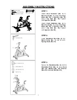
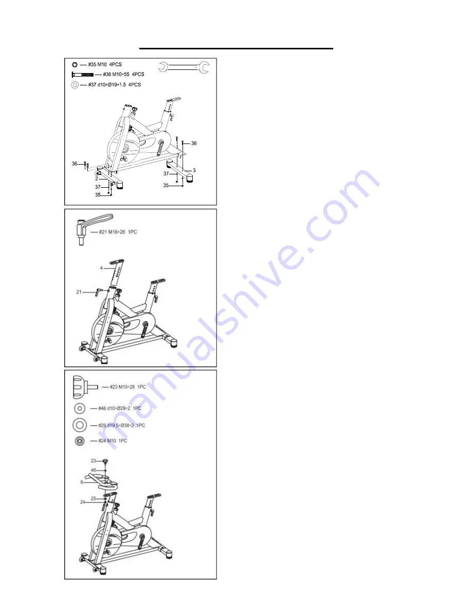
ASSEMBLY INSTRUCTIONS

#89 S14 S17 1PC

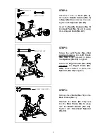
STEP 1:

Attach

Rear Stabilizer

(No. 3)

to

Main Frame

(No. 1)

using 2

Carriage

Bolts

(No. 36)

, 2

Washers

(No. 37)

and 2

Cap Nuts

(No. 35)

. Tighten

with

Spanner (No. 89)

.

Attach

Front Stabilizer (No. 2)

to

Main Frame

(No. 1)

using 2

Carriage

Bolts

(No. 36)

, 2

Washers

(No. 37)

and 2

Cap Nuts

(No. 35)

. Tighten

with

Spanner (No. 89)

.

STEP 2:

Insert

Handlebar Post (No. 4)

into

Main Frame

(No. 1)

and fix with

Spring Knob (No. 21)

.

STEP 3:

Secure the

Handlebar (No. 6)

onto the

Handlebar Post (No. 4)

using

Knob

(No. 23)

,

Washer (No. 46)

,

Washer

(No. 25)

and

Lock Nut (No. 24)

.

Summary of Contents for SF-B1714

Page 1: ...T DRIVE INDOOR CYCLING BIKE SF B1714 USER MANUAL IMPORTANT Read all instructions carefully before using this product Retain owner s manual for future reference For customer service please contact supp...

Page 2: ...e with a protective cover for your floor or carpet To ensure safety the equipment should have at least 2 feet 60 cm of free space all around it 5 Ensure that all nuts and bolts are securely tightened...

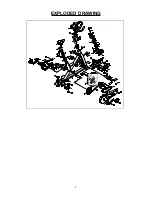
Page 3: ...2 EXPLODED DRAWING 16 88 14 82 72 43...

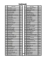
Page 4: ...1 pc 20L Left Pedal JD 304V 1 pc 66 Axis 20x155mm 1 pc 21 Spring knob M16x26 2 pcs 67 Wave Washer 21x27x0 3T 1 pc 22 L shaped knob M10x20 1 pc 68 Washer 20 5x25x0 5T 1 pc 23 Knob M10x28 1 pc 69 Hex B...

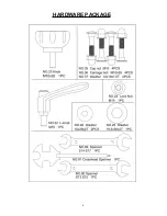
Page 5: ...4 HARDWARE PACKAGE...
Page 6: ...ith Spanner No 89 Attach Front Stabilizer No 2 to Main Frame No 1 using 2 Carriage Bolts No 36 2 Washers No 37 and 2 Cap Nuts No 35 Tighten with Spanner No 89 STEP 2 Insert Handlebar Post No 4 into Ma...

Page 7: ...L shaped knob No 22 STEP 5 Screw the Left Pedal No 20L counter clockwise into Left Crank No 18L Once screwed in place use Spanner No 90 to tighten Screw the Right Pedal No 20R clockwise into Right Cr...

Page 8: ...rt the bike as impact may cause damage to the equipment SEAT ADJUSTMENT Loosen the Spring Knob No 21 to raise or lower the Seat Post No 5 to the desired position Make sure the Seat Post No 5 secures i...

Page 9: ...may strip out threads over time and cause extensive damage Clean and lubricate pop pin assemblies Pull on the pin and spray a small amount of lubricant onto the pin Tighten the seat hardware making su...

Reviews: