background image


11 


PEDAL STRAP ADJUSTMENT


Your feet should be secured in the toe clips during exercise. Place 
your feet as far forward into the toe clips as you can. With your feet 
in place, turn the crank to bring one foot to within arm’s reach, grasp 
the pedal strap and pull it upward to tighten the toe clip cage. Then 
insert the strap back into the hoop of the toe clip. Repeat this 
process to secure your other foot.   


ADJUSTING THE RESISTANCE 

 
Adjust the resistance of the bike using the 

Tension Control Knob 

(No. C10)

. Increase the level of resistance by turning the 

Tension 

Control Knob (No. C10)

  to the RIGHT 

(clockwise), 

decrease the 

level of resistance by turning the 

Tension Control Knob (No.C10)


to the LEFT 

(counter-clockwise).


EMERGENCY BRAKE


During use, users can stop the bike completely by pushing down on 
the 

Tension Control Knob (No. C10)

. Pushing down on the 

Tension Control Knob (No. C10)

 will enforce the brake and bring 

the bike to an immediate stop.


TRANSPORTING THE BIKE


To move the bike, first ensure that the 

Handlebar (No. A06) 

is 

properly secured. If the handlebar is loose, tighten the [handlebar]

 T 

Shape Knob 2 (No. C15)

 to secure it. Next, stand at the front of the 

bike so that you’re directly in front of the handlebar. Firmly grasp 
and hold each side of the handlebar, place one foot on the 

Front 

Stabilizer (No. A02) 

and tilt the bike towards you until the 

Transportation Wheels (No. C08) 

on the 

Front Stabilizer (No. 

A02)

 touch the ground. With the 

Transportation Wheels (No. C08)


on the ground, you can transport the bike to the desired location 
with ease.


NOTE: 

When moving the bike, always use caution as unexpected 

impact, such as dropping the bike, may cause injury and affect the 
bike’s operation. 

DISMOUNTING 

For your safety, it is recommended that you never attempt to dismount or remove your feet from the 
pedals until both the flywheel and pedals/cranks have come to a complete stop. Failure to follow 
this recommendation may lead to loss of control and/or serious injury.   
   
Here are a few examples of how to safely dismount the bike: 
1. Reduce the pedal speed until the pedals/crank come to a complete stop. 
2. Increase the resistance until the pedals/crank come to a complete stop. 
3. Push and hold the 

Tension Control Knob


(No.  C10) 

down until the pedals/crank come to a 

complete stop.


Summary of Contents for SF-B1735

Page 1: ...SF B1735 USER MANUAL IMPORTANT Please retain owner s manual for maintenance and adjustment instructions Your satisfaction is very important to us PLEASE DO NOT RETURN UNTIL YOU HAVE CONTACTED US supp...

Page 2: ...equipment The equipment is designed for adult use only 4 Use the equipment on a solid flat level surface with a protective cover for your floor or carpet To ensure safety the equipment should have at...

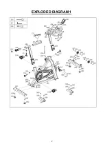
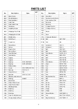
Page 3: ...2 EXPLODED DIAGRAM 1...

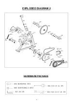
Page 4: ...3 EXPLODED DIAGRAM 2 HARDWARE PACKAGE...

Page 5: ...09 Inertial Axle 1 D03 Bolt M6 12 S5 2 B10 Septum 1 D04 Bolt M10 16 S6 4 B11 Septum 1 D05 Bolt M10 25 S6 4 B12 Bearing 6202 2RZ NBK 3 D06 Flat Washer D10 20 2 0 8 B13 Bearing 6205 2RS NBK 2 D07 Rivet...

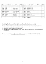
Page 6: ...d near the front of the manual Please contact us at support sunnyhealthfitness com or 1 877 90SUNNY 877 907 8669 No Description Spec QTY No Description Spec QTY D24 Nut M12 1 H6 S19 2 E01 Computer 1 D...

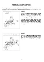
Page 7: ...B17 and remove the 4 Flat Washers No D06 from the Shipping Front Tube No A08 and Shipping Rear Tube No A09 You may save these Bolts No D04 Flat Washers No D06 Shipping Front Tube No A08 and the Shipp...

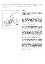
Page 8: ...Remove the 2 Nylon Nuts No D28L R located on the Pedals No C16L R Align the Left Pedal No C16L with the Left Crank Arm No B03L at 90 Screw the Left Pedal No C16L counter clockwise into its correspondi...

Page 9: ...tightening the T Shape Knob 2 No C15 Loosen and pull out the T Shape Knob 1 No C14 Insert the Seat Slider Tube No A05 into the Seat Post No A04 Adjust the Seat Slider Tube No A05 to the desired posit...

Page 10: ...puter No E01 onto the Computer Bracket No C18 located on the Handlebar No A06 Connect the Computer Wire a No E01a with the Sensor Wire No E05 Connect the Handle Pulse Wire No E02 with Computer Wire b...

Page 11: ...SEAT The seat of this bike is fully adjustable as it moves Up Down Fore forward Aft backward To adjust the height of the Seat Post No A04 loosen and pull the seat T Shape Knob 2 No C15 outward then ra...

Page 12: ...ured If the handlebar is loose tighten the handlebar T Shape Knob 2 No C15 to secure it Next stand at the front of the bike so that you re directly in front of the handlebar Firmly grasp and hold each...

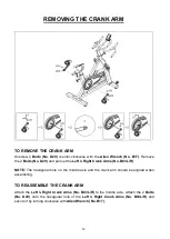
Page 13: ...eft Right Crank Arms No B03L R NOTE The hexagonal hole on the middle axle and the crank arm should be aligned when assembling TO REASSEMBLE THE CRANK ARM Attach the Left Right Crank Arms No B03L R to...

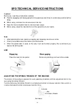
Page 14: ...hoe at a time 2 Check your pedals every time before you ride the bike 3 When the pedal starts to wear on the axle it will not function properly We recommend you replace the entire pedal USE Engaging D...

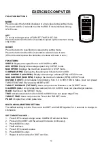
Page 15: ...average cadence RPM in STOP mode MAX CADENCE MAX RPM Displays the maximum cadence RPM in STOP mode DISTANCE DIST Accumulates total distance from 0 0 to 999 9 KM or Miles User can preset TARGET DISTANC...

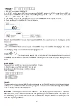
Page 16: ...current CADENCE is more than the TARGET CADENCE The bicycle icon will be displayed during exercise mode RACE MODE Press and hold MODE for 2 seconds to enter RACE mode In RACE mode only TIME and DIST...

Page 17: ...a small amount of lubricant onto the shaft 4 Tighten the seat hardware to make sure the seat is level and centered 5 Brush and treat the resistance pads Remove any foreign material that may have coll...

Page 18: ......

Reviews: