background image


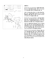
STEP 3 

Remove the pre-assembled 3 

Nylon Nuts (No. 

51)

 and 3 

Flat Washers (No. 50)

 from the back 

of the 

Seat (No. 68) 

with 

Spanner (No. A)

Attach the 

Seat (No. 68) 

to the 

Seat Tube (No. 

67)

  with  3 

Nylon  Nuts  (No.  51)

  and  3 

Flat 

Washers  (No.  50) 

that  were  removed.  Secure 

and tighten with 

Spanner (No. A)

Remove  the  pre-assembled  2 

Carriage  Bolts 

(No. 69)

, 2 

Flat Washers (No. 50)

, 2 

Cap Nuts 

(No. 4) 

and 2 

Spring Washers (No. 3) 

from the 

Backrest Tube (No. 70) 

with 

Spanner (No. A)

Attach the 

Backrest Tube (No. 70)

 to the 

Seat 

Tube (No. 67)

 with 2 

Carriage Bolts (No. 69)

, 2 

Flat Washers (No. 50)

, 2 

Spring Washers (No. 

3) 

and  2 

Cap  Nuts  (No.  4) 

that  were  removed. 

Secure and tighten with 

Spanner (No. A)

Remove  the  pre-assembled  4 

Screws  (No.  74)


and 4 

Flat Washers (No. 75)

 from 

Backrest (No. 

77) 

with

  Allen  Wrench  (No.  B)

.  Then  attach 

Backrest  (No.  77) 

to

  Backrest  Tube  (No.  70) 

with 4 

Screws (No. 74)

 and 4 

Flat Washers (No. 

75)

 that were removed. Secure and tighten with


Allen Wrench (No. B).


Summary of Contents for SF-B2710

Page 1: ...IMPORTANT Please retain owner s manual for maintenance and adjustment instructions Your satisfaction is very important to us PLEASE DO NOT RETURN UNTIL YOU HAVE CONTACTED US support sunnyhealthfitnes...

Page 2: ...e equipment The equipment is designed for adult use only 4 Use the equipment on a solid flat level surface with a protective cover for your floor or carpet To ensure safety the equipment should have a...

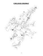
Page 3: ...2 EXPLODED DRAWING...

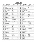
Page 4: ...y 1 68 Seat 1 22 Magnetic Bracket 152 1 3kg 1 69 Carriage Bolt M8 45 2 23 Curved Washer 17 5 21 0 3 1 70 Backrest Tube 1 24 Nut M10 3 71 Cap 30 30mm 1 25 Adjustable Nut 2 72 Cap 15 30mm 4 26 Flat Wash...

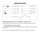
Page 5: ...in order for us to accurately identify the part s needed The model number found on cover of manual The product name found on cover of manual The part number found on the EXPLODED DIAGRAM and PARTS LIS...

Page 6: ...4 Secure and tighten with Spanner No A STEP 2 The Left Pedal No 12L is marked L and the Right Pedal No 12R is marked R Turn the resistance knob all the way to the right until the cranks are immobiliz...

Page 7: ...ap Nuts No 4 and 2 Spring Washers No 3 from the Backrest Tube No 70 with Spanner No A Attach the Backrest Tube No 70 to the Seat Tube No 67 with 2 Carriage Bolts No 69 2 Flat Washers No 50 2 Spring Wa...

Page 8: ...67 into Rear Main Frame No 54 Insert and tighten Release Knob No 45 to secure STEP 5 Attach Handlebar No 84 to the Front Main Frame No 55 with 4 Screws No 87 2 Flat Washers No 75 2 Curved Washers No...

Page 9: ...Insert Sensor Wire No 39 into the hole on the back of the Meter No 86 Make sure the wire does not get caught when you attach the meter Insert Hand Pulse Wire No 83 into the hole on the back of the Met...

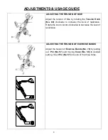
Page 10: ...80 clockwise to increase the level of resistance Rotate the knob counter clockwise to decrease the level of resistance ADJUSTING THE TENSION OF EXERCISE BANDS Adjust the tension of Exercise Bands No...

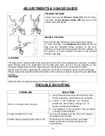
Page 11: ...ectrical hazard or electronics to failure Please keep the bike especially the computer out of direct sunlight to prevent screen damage Please inspect all assembly bolts and pedals on the machine weekl...

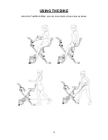
Page 12: ...11 USING THE BIKE Using the Total Body Bike you can do a variety of exercises as below...

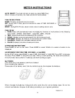
Page 13: ...miles 5 CALORIES Displays the estimated calories burned 6 PULSE Displays your pulse in beats per minute OPERATING INSTRUCTIONS Press MODE to turn on the meter Press MODE to select SCAN or to select a...

Reviews: