background image

- 5 - 


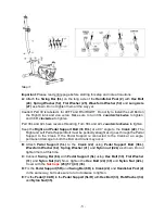
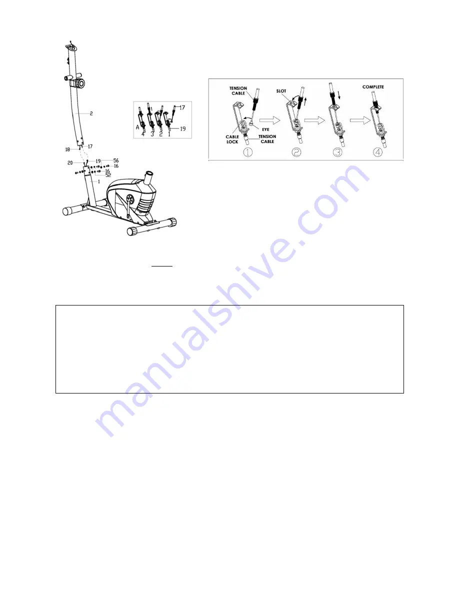
Step 3: 
 

Important: 

Please read entire page before starting this step and note all cautions. 

A:

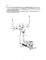
 Attach the 

Swing Bar (6L)

 on the long axle of the 

Handlebar Post (2)

 with 

Hex Bolt 

(24)

Spring Washer (52)

Flat Washer (25)

Waveform Washer (54)

 and 

Long Axle 

(27)

 as shown. Do not tighten them all the way yet. 

Caution! Part 38 is labeled L for LEFT and R for RIGHT. Do not try to install the Left Bolt on 

the  Right  Crank  and  vice  versa.  Make  sure  to  turn  38L 

counterclockwise

  to  tighten, 

and 38 R 

clockwise

 to tighten. 

Part 38L and 42L have reverse threading. Turn 38L and 42L 

counterclockwise

 to tighten.   

Keep the 

Right and Pedal Support Bolt (38 R/L)

 at a 90° angle to the 

Crank (22)

. The 

Right and Left Pedal Support Bolt must be perfectly straight as it goes through the Pedal 
Support  to  the  Crank.  If  the  Pedal  Support  is  connected  to  the  Crank  at  an  angle, 
permanent damage to both the Bolt and Crank may occur. 

B:

  Attach 

Pedal  Support  (5L)

  to  the 

Crank  (22)

  using 

Pedal  Support  Bolt  (38L)

Waveform Washer (62)

Spring Washer (41)

 and 

Nylon nut (42L)

 as shown. Do not 

tighten them at this time. 

C:

 Connect 

Swing Bar (6L)

  with 

Pedal Support (5L)

 using 

Hex Bolt (30)

Flat Washer 

(31)

  and 

Nylon  Nut  (32)

.  Now,  tighten  the 

Hex  Bolt  (24)  (30)

  and 

Nylon  Nut  (42L)

Cover with the 

Nut Caps

 (23) (57) (43) (36)

D:

 Fix the 

Pedal Support (5R)

 and 

Swing Bar (6R)

 to 

Crank (22)

 and 

Handlebar Post (2)


in the same way, but make sure to turn clockwise to tighten. 

E:

 Fix the 

Pedal (10L/R)

 to the 

Pedal Support (5L/R)

 with 

Hex Bolt (33)

Flat Washer (34)


and 

Nylon Nut (35)


Summary of Contents for SF-E3628

Page 1: ...gned for reverse pedaling Failure to comply with this warning may result in permanent damage to your new equipment IMPORTANT Read all instructions carefully before using this product Retain owner s ma...

Page 2: ...le the machine or repair any parts of machine Remove drops of sweat from the machine immediately after finishing training 7 Your health can be affected by incorrect or excessive training Consult a doc...

Page 3: ...2 EXPLODED DIAGRAM...

Page 4: ...crew M5X45 1 52 Spring washer D8 8 22 Crank 1 53 Handlebar chuck cover 1 23 Nut cap S14 4 54 Waveform washer 20X 28X0 3 2 24 Hex bolt M8X15 2 55 Cross screw M4X12 4 25 Flat washer 8 2X 32 X2 2 56 Arc...

Page 5: ...d Acorn Nuts 14 Step 2 Check the Tension Controller 17 is at Level 1 lowest resistance to ensure the cable is the longest Connect the Sensor Wire 20 with Extension Wire 18 Then connect Tension Cable 1...

Page 6: ...angle to the Crank 22 The Right and Left Pedal Support Bolt must be perfectly straight as it goes through the Pedal Support to the Crank If the Pedal Support is connected to the Crank at an angle per...

Page 7: ...6...

Page 8: ...of the hole of the computer bracket Fix the Armrest 8 on the Handlebar Post 2 with Hex Screw 51 Spring Washer 52 and Flat Washer 31 and then cover with the Handlebar Chuck Cover 53 B Attach the Handl...

Page 9: ...Step 5 Connect the Pulse Sensor Wire 50 and Extension Wire 18 with the wires coming from the Computer 9 and then fix the Computer 9 onto the computer bracket of the Handlebar Post 2 with Cross Screw...

Page 10: ...9 To move the elliptical hold by the handles of the Armrest 8 Tilt the elliptical until the wheels of the Front Stabilizer 3 touch the floor Then you can wheel the elliptical to the desired location...

Page 11: ...OCK MODE setting press the MODE key when the pointer on the function you wish to select begins to blink once locked only the selected function will be displayed 4 FUNCTIONS TIME Counts the total time...

Reviews: