background image


BATTERY INSTALLATION & REPLACEMENT


BATTERY INSTALLATION: 


The 

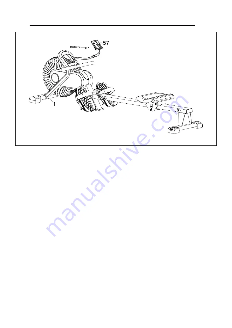
Computer  (No.  57) 

uses  1  AAA  battery.  Remove  the 

Computer  (No.  57)

  from  the 

Main 

Frame (No. 1)

. Then put 1 battery into battery compartment. Make sure the (+) and (-) poles of the 

battery is in the correct position. Finally put the 

Computer (No. 57)

 back into the 

Main Frame (No. 

1)

 
The installation is complete! 
 

BATTERY REPLACEMENT: 

 
If there is a problem with the display, try changing the battery first. Remove the 

Computer (No. 57)


from the 

Main Frame (No. 1)

. Then remove the old battery, and replace with new battery. Make 

sure the (+) and (-) poles of the battery is in the correct position. Finally put the 

Computer (No. 57)


back into the 

Main Frame (No. 1)

 
The replacement is complete! 
 

NOTE:

 Do not mix battery types and do not mix old and new batteries. Dispose batteries according 

to your state and regional guidelines. 


Summary of Contents for SF-RW520050

Page 1: ...ER MANUAL IMPORTANT Please retain owner s manual for maintenance and adjustment instructions Your satisfaction is very important to us PLEASE DO NOT RETURN UNTIL YOU HAVE CONTACTED US support sunnyhea...

Page 2: ...equipment The equipment is designed for adult use only 4 Use the equipment on a solid flat level surface with a protective cover for your floor or carpet To ensure safety the equipment should have at...

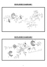
Page 3: ...2 EXPLODED DIAGRAM 1 EXPLODED DIAGRAM 2...

Page 4: ...3 HARDWARE PACKAGE...

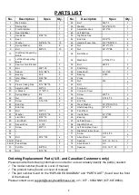
Page 5: ...er 6 2 59 Screw M5 15 2 22 Nut M6 2 60 Screw ST4 2 15 5 23 Screw ST4 2 20 8 61 End Cap 1 24 End Cap 2 62 Wave Washer 18 10 2 0 3 1 25 End Cap 1 63 Shaft Snap Ring 12 1 0 2 26 Bolt M6 15 4 64 Fan Wheel...

Page 6: ...with Allen Wrench No 72 Attach the Front Stabilizer No 3 to the Main Frame No 1 using 2 Bolts No 9 and 2 Washers No 7 that were removed Tighten and secure with Allen Wrench No 72 STEP 2 Insert the 2 B...

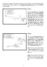
Page 7: ...o 2 attach another Limit Pad No 28 to right side of Limit Shaft No 29 with 1 Washer No 27 and 1 Bolt No 26 Tighten and secure with the Spanner No 73 STEP 4 Turn over the Sliding Rail No 2 with Seat No...

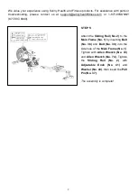
Page 8: ...com or 1 877 90SUNNY 877 907 8669 STEP 5 Attach the Sliding Rail No 2 to the Main Frame No 1 by inserting Bolt No 38 and Bolt No 39 into the side hole of the Main Frame No 1 Tighten with Allen Wrench...

Page 9: ...o 36L R remove the velcro ends of the strap from the mesh side Once removed you may adjust the Pedal Straps No 36L R to fit the user s foot size then securing the velcro end of Pedal Straps No 36L R b...

Page 10: ...The installation is complete BATTERY REPLACEMENT If there is a problem with the display try changing the battery first Remove the Computer No 57 from the Main Frame No 1 Then remove the old battery a...

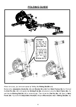
Page 11: ...ding Rail No 2 where it joins the Main Frame No 1 and fold the Sliding Rail No 2 to vertical angle Then insert the Pull Pin No 37 back to Main Frame No 1 and fix the Adjustable Knob No 41 and Washer N...

Page 12: ...utton is pressed FUNCTION TIME Counts the rowing time during current workout COUNT Counts the rowing strokes from current workout CALORIE Counts the total calories burned from current workout REPS MIN...

Page 13: ......

Reviews: