background image

7

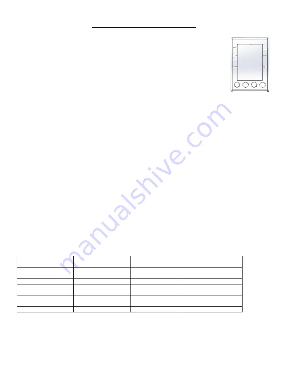
EXERCISE COMPUTER

BUTTON FUNCTION

MODE:

Press to enter setting value.

Press to select main display function.

Press and hold for 3 seconds to reset all function values.

SET:

Press to set desired function values.

Press and hold to set function values quicker.

RESET:

Press to reset function value.

Press and hold for 3 seconds to reset all function values.

RECOVERY:

Press to start Pulse Recovery Function (while the heart rate function is activated).

NOTE:

Pulse Recovery Function requires prior heart rate measurement. Pulse Recovery Function

cannot be activated without heart rate measurement.

FUNCTION

SCAN:

Automatically cycles through functions in a pre-set order, displaying each function for 6

seconds (then repeats).

STOP:

The word

“STOP”

will appear whenever rowing has stopped.

STROKES:

Accumulates the amount of strokes during workout, from start to finish.

STROKES /MIN:

Displays the current strokes and stroke pace/average per minute.

TIME:

Accumulates the total time of an exercise from start to finish.

TIME / 500M:

Displays the projected completion time of a 500m distance based on your current stoke

rate/pace.

DISTANCE:

Accumulates the total distance of an exercise from start to finish.

CALORIES:

Accumulates the total amount of calories burned during an exercise.

PULSE:

Displays current heart rate. A

Heart Rate Transmitter Belt

is required in order for the Pulse

function to be used. Any transmitter belt with 5.3KHz frequency is compatible. Pulse cannot be

displayed without use of belt. (NOTE: Heart Rate Transmitter Belt is NOT included).

HEART SIGN:

Displayed on monitor along with your current heart rate. (

Heart Rate Transmitter Belt

required in order for Heart Sign and heart rate to be displayed on monitor during exercise).

SPECIFICATION:

Function

Max. display values

Setting of values

Value stored as long as

not reset to 0

STROKES

0~9999

0~9990 in 10 step

Yes

STROKES /MIN

0~999

Not possible

No

TIME/500M

0:00~99:59

Not possible

No

TIME

0:00~99:59

0:00~99:00 in 1 min.

step

Yes

DISTANCE

0:00~99.99

0~99.50 in 0.5 step

Yes

CALORIES

0~9999

0~9999 in 10 step

Yes

PULSE

60~220

60~220 in 1 step

Yes

Summary of Contents for SF-RW5508

Page 1: ...SER MANUAL IMPORTANT Please retain owner s manual for maintenance and adjustment instructions Your satisfaction is very important to us PLEASE DO NOT RETURN UNTIL YOU HAVE CONTACTED US support sunnyhealthfitness com or 1 877 90SUNNY 877 907 8669 ...

Page 2: ...e equipment The equipment is designed for adult use only 4 Use the equipment on a solid flat level surface with a protective cover for your floor or carpet To ensure safety the equipment should have at least 2 feet 60CM of free space all around it 5 Ensure that all nuts and bolts are securely tightened before using the equipment The safety of the equipment can only be maintained if it is regularly...

Page 3: ...2 EXPLODED DIAGRAM HARDWARE PACKAGE ...

Page 4: ... 50 End Cap Φ22 16 1 15 Idler Wheel Connect Staff 1 51 Refer to 123 16 Nut M10 1 0 H6 1 52 N A 17 Inertial Wheel 5 Φ240 129 1 53 N A 18 Pulling Spring Φ2 2 Φ18 65 1 54 N A 19 Idler Wheel Φ42 Φ35 Φ12 24 1 55 N A 20 Washer D6 Φ16 1 5 1 56 N A 21 Bolt M6 12 S10 1 57 Screw M8 40 S6 1 22 N A 58L R Cover L R 2 23 Grommet Φ16 2 59 Screw ST4 2 19 Φ8 7 24 N A 60 Washer D4 Φ9 1 0 2 25 N A 61 N A 26 N A 62 N...

Page 5: ...Belt Wheel 1 87 Nut M6 H6 S10 2 113 Wave Washer D10 Φ15 0 3 1 88 Screw M6 16 S5 2 114 PC board for Mesh Belt Wheel 1 89 Screw M5 16 Φ10 1 115 Bearing 6300 2RS 1 90 N A 116 C Clip d35 1 91 Wave Washer D12 Φ15 5 0 3 1 117 Mesh Belt Plate 1 92 Screw ST4 2 16 Φ8 6 118 Bearing 16003 2RS 2 93 Bottom Hanger 100 38 90 1 119 Bearing 1 94 Below Fixed Board 41 8 15 94 1 120 Belt wheel 1 95 Top Hanger 100 44 ...

Page 6: ...asher No 76 and 2 Locating Mounts No 75 from Aluminum Rail No 73 using Allen Wrenches No 103 No 102 Attach Seat No 65 onto Aluminum Rail No 73 Next re install 2 Locating Mounts No 75 Axel No 74 Washer No 76 and Bolt No 71 to Aluminum Rail No 73 Tighten and secure Bolt No 71 using Allen Wrenches No 103 No 102 Attach Back Stand No 80 to Aluminum Rail No 73 using Screw No 89 and Screw No 79 Tighten a...

Page 7: ...rame No 73 to the same level see Figure 1 and connect the two sections together When connecting the two sections the notch see Figure 2 on Bottom Hanger No 93 must be placed onto the lower Bolt Tube No 97 first then lower Top Hanger No 95 into place up against the upper Bolt Tube No 97 See Figure 2 Slowly lower both sections until they connect securely and push them down into place Insert Pull Pin...

Page 8: ... the total time of an exercise from start to finish TIME 500M Displays the projected completion time of a 500m distance based on your current stoke rate pace DISTANCE Accumulates the total distance of an exercise from start to finish CALORIES Accumulates the total amount of calories burned during an exercise PULSE Displays current heart rate A Heart Rate Transmitter Belt is required in order for t...

Page 9: ...f automatically 4 Time Distance and Calorie functions can only be set one at a time For example if you set one function then proceed to set another function the first set function will automatically be reset to zero 5 If the pre set value for STROKES TIME DISTANCE or CALORIES counts down to zero the related value in function window will flash for 10 seconds to remind you and then begin counting up...

Page 10: ...rer s instructions for wearing and using the Heart Rate Transmitter to obtain an accurate reading Pulse Recovery function is used upon completion of a workout The function measures the amount of time it takes for the user s heart rate to return to a resting heart rate the quicker the user s heart rate returns to a resting rate the better Press the RECOVERY button while the PULSE function is activa...

Page 11: ... return the computer to position A Rotate Tension Control No 42 clockwise to increase the level of resistance rotate the tension control counter clockwise to decrease the level of resistance Level 1 is the lowest and level 10 is the highest REPLACE THE BATTERY To replace the battery remove Computer No 1 from Main Frame No 37 Press the top end of Computer No 1 When the bottom end sticks out hold Co...

Reviews: