


12
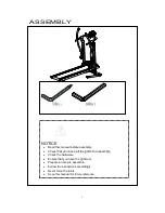
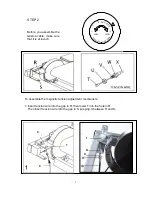
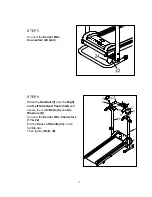
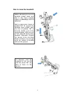
STEP 5
Connect the
Sensor Wire
Connectors (24 & 22)
.
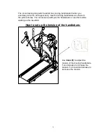
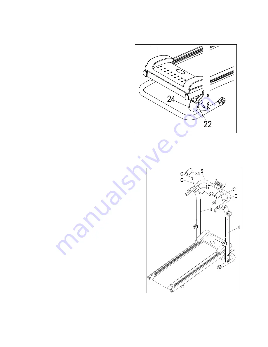
STEP 6
Place the
Handrail (5)
onto the
Right
and Left Side Hand Posts (3&4)
and
secure them with
Bolts (C)
and
Arc
Washers (G)
.
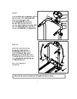
Connect the
Sensor Wire Connectors
(17 & 22)
.
Put the
Cover of Handle (34)
on the
handle bar
.
Then tighten
Bolts (E).
E
Summary of Contents for SF-T7614
Page 2: ......
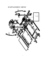
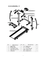
Page 4: ...2 EXPLODED VIEW 9 S R...
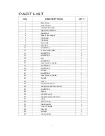
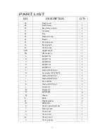
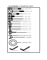
Page 9: ...7 ASSEMBLY PARTS LIST 5 5...
Page 22: ......


