background image


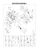
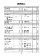
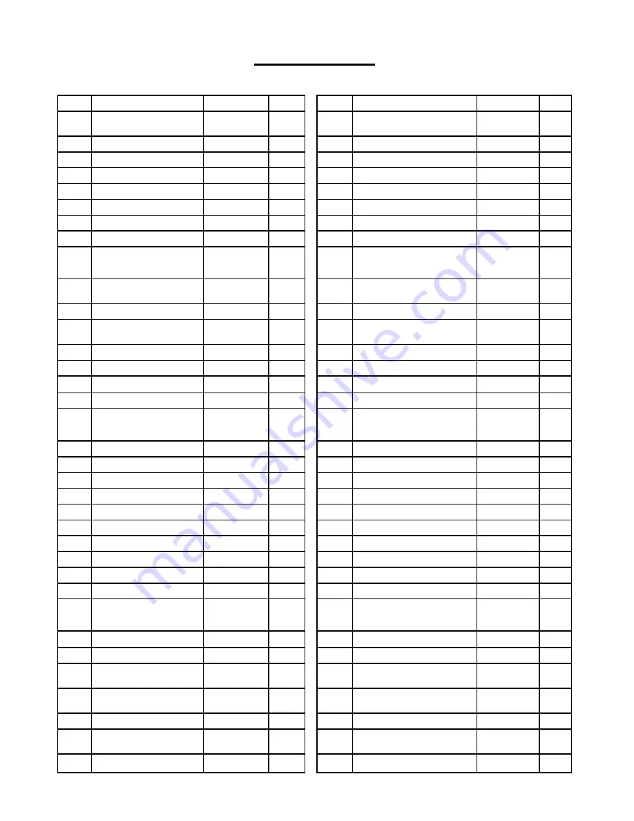
PARTS LIST 

No. 

Description 

Spec. 

Qty    No. 

Description 

Spec. 

Qty 

A01 

Base Frame 


C24 

Safety Key Bottom 
Cover 


A02 

Main Frame 


C25 

Safety Key 


A03 

Left Handrail Frame 


C26 

Handrail Left Cover 


A04 

Right Handrail Frame 


C27 

Handrail Right Cover 


B01 

Front Roller 


C28 

Handrail Outer Cover 


B02 

Rear Roller 


C29 

Handrail Inner Cover 


B03 

Cylinder 


C30 

Support Fastener 


B04 

Allen Wrench 

5mm   


C31 

Plastic Gasket 


B05 

Front Base Secure 

Shaft 


1   


C33 

Bushing 


B06 

Safety Key Spring 
Gasket   


D01 

Console 


B07 

Adjustment Knob   


D02 

Control Board 


B08 

Ball Pin 


D03 

Console Communication 
Wire 


C01 

Motor Top Cover 


D04 

Remote Control 


C02 

Left Side Rail Plug 


D05 

DC Motor 


C03 

Right Side Rail Plug 


D06 

AC Single Line 

Blue 

C04 

Motor Cover Board   


D07 

AC Single Line 

Brown 

C05 

Plastic Insulation 

Block 


D08 

Square Switch 


C06 

Transportation Wheel 


D09 

Running Board   


C07 

Front Board   


D10 

Magnetic Ring 


C08 

Side Rail 


D11 

Magnetic Core 


C09 

Running Belt 


D12 

Power Socket 


C10 

End Foot Pad 


D13 

Overload Protector 


C11 

Motor Belt 


D14 

Power Wire 


C12 

Left End Cap 


D15 

Inverted Switch   


C13 

Right End Cap 


D16 

AC Single Line 

Blue 

C14 

Black Cushion 


D17 

AC Single Line 

Brown 

C15 

Foot Pad 


D18 

Grounding Wire 


C16 

Black Cushion 

Column 


D19 

Button   


C17 

Table Core Cover 


D20 

Button Switch Board   


C18 

Grating


D21 

Left Handrail Top Wire 


C19 

Module Switch Button 


D22 

Left Handrail Middle 
Wire 


C20 

Motor Cover Right 
Board   


D23 

Left Handrail Bottom 
Wire 


C21 

Handrail Top Cover 


D24 

Right Handrail Top Wire 


C22 

Handrail Bottom 
Cover 


D25 

Right Handrail Middle 
Wire 


C23 

Safety Key Top Cover 


E20 

Big Washer 

Summary of Contents for SF-T7971

Page 1: ...971 USER MANUAL IMPORTANT Please retain owner s manual for maintenance and adjustment instructions Your satisfaction is very important to us PLEASE DO NOT RETURN UNTIL YOU HAVE CONTACTED US support sunnyhealthfitness com or 1 877 90SUNNY 877 907 8669 ...

Page 2: ...he manufacturer 3 Never operate this treadmill if it has a damaged cord or plug if it is not working properly if it has been dropped or damaged or dropped into water Return this treadmill to a service center for examination for repair 4 Keep the cord away from heated surfaces 5 Never operate the treadmill with the air openings blocked Keep the air openings free of lint hair and alike items 6 Never...

Page 3: ... solid flat level surface with a protective cover for your floor or carpet To ensure safety the equipment should have at least 8 feet 240CM of free space behind it and 2 feet 60 CM on each side Do not place the treadmill on any surface that blocks air openings To protect the floor or carpet from damage place a mat under the treadmill 5 Ensure that all nuts and bolts are securely tightened before u...

Page 4: ...t once it s in motion 6 A safety key is provided for emergency use The treadmill will function only if the safety key is inserted into the console In case of emergency remove the safety key to immediately stop the running belt and shut off the treadmill The display screen will reset once the safety key is reinserted 7 This treadmill is designed for adult use only Children should not be allowed to ...

Page 5: ...4 EXPLODED DIAGRAM 1 ...

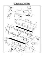
Page 6: ...5 EXPLODED DIAGRAM 2 ...

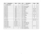
Page 7: ... Blue 1 C04 Motor Cover Board 1 D07 AC Single Line Brown 1 C05 Plastic Insulation Block 2 D08 Square Switch 1 C06 Transportation Wheel 2 D09 Running Board 1 C07 Front Board 1 D10 Magnetic Ring 1 C08 Side Rail 2 D11 Magnetic Core 1 C09 Running Belt 1 D12 Power Socket 1 C10 End Foot Pad 2 D13 Overload Protector 1 C11 Motor Belt 1 D14 Power Wire 1 C12 Left End Cap 1 D15 Inverted Switch 1 C13 Right En...

Page 8: ...9 8 1 E07 Bolt M6 55 3 E28 Flat Washer 3 1 E08 Bolt M6 45 2 E29 Screw ST2 5 6 4 E09 Bolt M6 35 4 E30 Washer Ф10 4 E10 Bolt M6 25 2 E31 Nut M10 2 E11 Bolt M6 15 2 E32 Gasket 54 2 E12 Bolt M5 12 8 E33 Screw ST4 2 8 2 E13 Bolt M5 10 9 E34 Screw ST2 9 4 2 E14 Screw ST4 2 20 7 H01 Filter 1 E15 Screw ST4 2 12 6 H02 AC Single Line 1 E16 Screw ST4 2 12 9 H03 AC Single Line 1 E17 Screw ST4 2 12 4 H04 Groun...

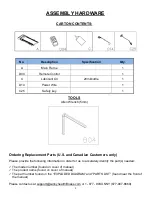
Page 9: ...rt s needed The model number found on cover of manual The product name found on cover of manual The part number found on the EXPLODED DIAGRAM and PARTS LIST found near the front of the manual Please contact us at support sunnyhealthfitness com or 1 877 90SUNNY 877 907 8669 No Description Specification Qty A Main Frame 1 D04 Remote Control 1 C Lubricant Oil 20ml bottle 1 D14 Power Wire 1 C25 Safety...

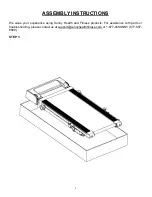
Page 10: ... INSTRUCTIONS We value your experience using Sunny Health and Fitness products For assistance with parts or troubleshooting please contact us at support sunnyhealthfitness com or 1 877 90SUNNY 877 907 8669 STEP 1 ...

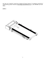
Page 11: ...10 We value your experience using Sunny Health and Fitness products For assistance with parts or troubleshooting please contact us at support sunnyhealthfitness com or 1 877 90SUNNY 877 907 8669 STEP 2 ...

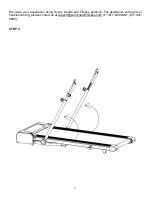
Page 12: ...11 We value your experience using Sunny Health and Fitness products For assistance with parts or troubleshooting please contact us at support sunnyhealthfitness com or 1 877 90SUNNY 877 907 8669 STEP 3 ...

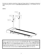
Page 13: ...cessary to adjust the length of the Left Handrail No G01 hold the Adjustment Knob No B07 with one hand and rotate until it becomes loosened Pull the Adjustment Knob No B07 outward and hold Left Handrail No G01 with your other hand Pull upward until the Adjustment Knob No B07 clicks on the handrail Tighten the Adjustment Knob No B07 up once desired length is achieved Adjust the Right Handrail No G0...

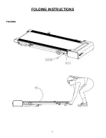
Page 14: ...13 FOLDING INSTRUCTIONS FOLDING ...

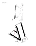
Page 15: ...14 UNFOLDING ...

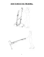
Page 16: ...15 HOW TO MOVE THE TREADMILL ...

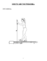
Page 17: ...16 HOW TO USE THE TREADMILL WITH HANDRAILS ...

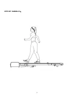
Page 18: ...17 WITHOUT HANDRAILS ...

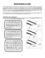
Page 19: ... check if the Running Belt No C09 drifts from the center Use Allen Wrench No B04 to adjust 1 If the Running Belt No C09 drifts to the right turn the right adjusting bolt turn clockwise then turn the left adjusting bolt turn counter clockwise If the Running Belt No C09 does not move repeat this step until it centers Refer to Figure A 2 If the Running Belt No C09 drifts to the left turn the left adj...

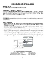
Page 20: ...oard No D09 Repeat this process for the other side 2 The moving parts should turn freely and quietly Abnormality of moving parts will affect the safety of the equipment Inspect and tighten all bolts regularly 3 To better maintain the treadmill and prolong its lifespan it is suggested that maintenance be done on a regular basis 4 DO NOT LOOSEN OR MAKE ANY ADJUSTMENTS TO THE RUNNING BELT WHILE APPLY...

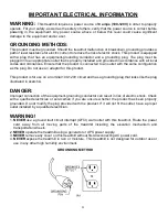
Page 21: ...guration as the plug Do not use an adaptor for this product This product is for use on a nominal 100 120V circuit and has a grounding plug that looks like the plug illustrated in sketch A DANGER Improper connection of the equipment grounding conductor can result in risk of electric shock Check with a qualified electrician or serviceman if you are unsure whether the product has been properly ground...

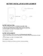
Page 22: ...ve end facing up 4 Put the battery cover back on to the battery holder The installation is complete BATTERY REPLACEMENT 1 Remove the battery cover from the back of the Remote Control No D04 2 Remove the old battery and install the new battery into the battery holder with the positive end facing up 3 Put the battery cover back on to the battery holder The installation is complete Dispose the old ba...

Page 23: ... treadmill Before attempting to use the treadmill take some time to familiarize yourself with the controls 1 Once you get on you can stand with your feet on the side rails and stabilize yourself by holding onto the Left Right Handrails No G01 No G02 2 Next attach the clip end of the Safety Key No C25 to your clothes and insert the magnetic end of the Safety Key No C25 into the console 3 Press the ...

Page 24: ...ight of the mode window will be lit CONSOLE FUNCTIONS 1 STANDBY MODE the treadmill is waiting for the input command You can use the remote control to switch to manual mode 2 MANUAL MODE You can use the remote control to start pause stop the treadmill as well as increase or decrease the speed NOTE When attempting to get off of the treadmill but you do not press the Start Pause button the treadmill ...

Page 25: ...0 1 MPH Miles per hour Pressing and holding either of these buttons for a duration of over a second will increase or decrease the speed continually 3 STOP BUTTON When in use press the STOP button to terminate your workout session All data will be deleted and reset to the initial setting 4 MODE a When in stop mode you can press this button to switch between Standby Mode and Manual Mode b When runni...

Page 26: ...88 miles The system will release a beeping sound every 10 seconds and displays an OIL icon on your LCD display Please read the LUBRICATING THE TREADMILL instructions on Page 19 to learn the proper steps to lubricate your treadmill Apply the lubricant oil to the middle of the running board on both sides After application press and hold the STOP button for 3 seconds to clear the reminder POWER SAVE ...

Page 27: ... to replace it If the problem is not rectified you may need to replace the bottom control board E02 Burst clash protection Incoming voltage is lower than 50 of the required voltage Check that the incoming power supply is the correct voltage E05 Current overload protection Self Protecting System The incoming voltage is too low or too high The control board is damaged Restart the treadmill Check the...

Page 28: ...replace it If the problem is not rectified you may need to replace the control board E09 Inversion error The treadmill sets upright or not placed horizontally Adjust the treadmill and place it horizontally The wires of the control board are not connected well Replace the control board E10 Motor Abnormality The motor is damaged or a moving part of the treadmill is stuck and therefore the motor is u...

Page 29: ......
Reviews: