6
Installation & Operation Manual for the
Active Vibration Cancellation (AVC) System
Attach the Wiring Harnesses
The components of the AVC system are interconnected with the cryocooler and with other interfacing equipment
using the two supplied wiring harnesses: the power wiring harness, and the instrumentation wiring harness.
Power Wiring Harness
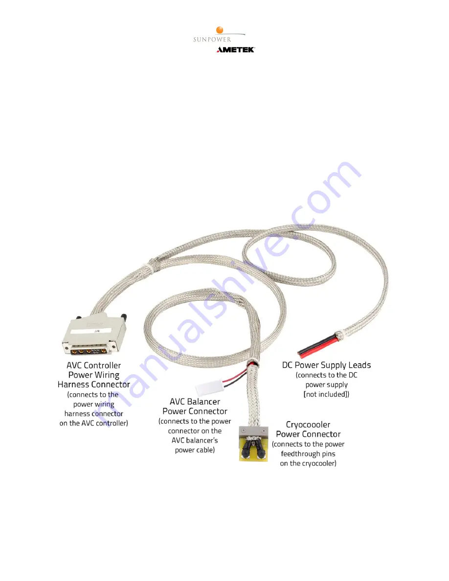
The power wiring harness (figure 6) has four connections:
•
DC Power Supply Leads
– A black lead and a red lead that connect to the DC power supply [not included]
for the cooler.
•
AVC Controller Power Wiring Harness Connector
– A D-sub connector with various pin sizes that connects
to the power wiring harness connector on the AVC controller.
•
Cryocooler Power Connector
– A two-pin connector that mounts to the back plate of the cryocooler and
connects to the two feedthrough pins used to power the cryocooler.
•
AVC Balancer Power Connector
– A small, two-conductor white plastic connector that connects to the pow-
er connector on the AVC balancer’s power cable (figure 2).
Figure 6. Power Wiring Harness


