background image


Installation & Operation Manual for the 


Active Vibration Cancellation (AVC) System 

Instrumentation Wiring Harness 

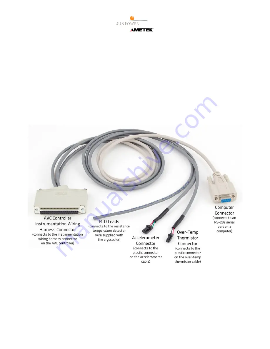
The instrumentation wiring harness (figure 7) has five connections: 

• 

Computer Connector

 – A molded plastic, 9-pin, female RS-232 serial communications connector that con-

nects to an RS-232 serial port on a computer for relaying control commands and replies. 

• 

AVC Controller Instrumentation Wiring Harness Connector

 – A molded plastic 37-pin D-sub connector 

that connects to the instrumentation wiring harness connector on the AVC controller. 

• 

Over-Temp Thermistor Connector

 – A small, black, two-pin plastic connector that connects to the plastic 

connector on the over-temp thermistor cable. 

• 

Accelerometer Connector

 – A small, black, three-pin plastic connector that connects to the plastic connector 

on the accelerometer cable. 

• 

RTD Leads

 – Four leads that connect to the Resistance Temperature Detector (RTD) wire supplied with the 

cryocooler. The RTD wire is attached to an RTD which is attached to the thermal load or to the cryocooler’s 
cold tip as described in the cryocooler installation and operation manual. 


Figure 7. Instrumentation Wiring Harness 


Summary of Contents for AMETEK AVC

Page 1: ...Installation Operation Manual for the Active Vibration Cancellation AVC System Rev December 15 2014...

Page 2: ...Section 1 Equipment Description 3 System Components 3 Specifications 3 Section 2 Installation 4 Install the AVC Balancer 4 Install the Accelerometer 5 Attach the Wiring Harnesses 6 AVC Controller Over...

Page 3: ...ncludes an AVC balancer AVC controller over temp thermistor cable accelerometer cable power wiring harness and instrumentation wiring harness as shown in figure 1 Figure 1 Active Vibration Cancellatio...

Page 4: ...er from the cryocooler Now install the AVC balancer as follows 1 Unscrew and remove the hex standoff from the balancer figure 2 2 Screw the hex standoff onto the cryocooler end plate 3 Place the balan...

Page 5: ...ate of the CryoTel cryocooler with the provided 5 40 bolt into the end plate of the cryocooler figure 5 If the cryocooler is an older model not equipped with a 5 40 threaded hole then use a small amou...

Page 6: ...y Leads A black lead and a red lead that connect to the DC power supply not included for the cooler AVC Controller Power Wiring Harness Connector A D sub connector with various pin sizes that connects...

Page 7: ...s to the instrumentation wiring harness connector on the AVC controller Over Temp Thermistor Connector A small black two pin plastic connector that connects to the plastic connector on the over temp t...

Page 8: ...among the features of the standard CryoTel controllers is the reject over temperature alarm A provided thermistor figure 9 is attached to the cooling fins via the available threaded hole or near the w...

Page 9: ...Installation Operation Manual for the 9 Active Vibration Cancellation AVC System Figure 9 Over Temp Thermistor Cable Figure 10 Thermistor Attached to the Cryocooler with Epoxy...

Page 10: ...ol status of the controller a Command COOLER CR b This command displays the current control status of the controller Control Modes OFF The cryocooler is OFF or being powered down and turned OFF ON The...

Page 11: ...ag is active The LCD will flicker ON and OFF at approximately 0 4s interval The LCD s content will toggle between the regular data and an error screen The error screen will have the ERROR command s ou...

Page 12: ...l constant of the temperature control loop a Command KP CR b Returns the proportional constant of the temperature control loop 10 Set the proportional constant of the temperature control loop a Comman...

Page 13: ...Set User lock state a Command LOGOUT PASSWORD CR b Disable access to the commands designated as User locked c A return of 1 confirms that controller parameters are locked d PASSWORD is the current use...

Page 14: ...cked c Set commanded power when in power control mode as set by the COOLER POWER command d VAL is the target power in watts While any number from 0 0 to 999 99 can be input the controller will only co...

Page 15: ...s 25 Display target temperature in kelvin a Command TTARGET CR b Returns the target temperature of the controller in kelvin when in temperature control mode default mode 26 Set target temperature a Co...

Reviews: