D-AUX
RS-485
2-Wire
LAN1
RS-485
2/4-Wire
WAN/
LAN2
SMA/ABB/METER/
OTHER (2-W)
INSTALLER
COMPUTER
FRONIUS (4-W)/
METER/OTHER
HOMEOWNER
ROUT
ER
Routing Wire and Cable
•
Any openings in the enclosure must be filled with
Type 4 or better rated components to maintain the
integrity of the enclosure’s environmental system
• Drill extra openings with appropriate knockout tools
(
do not use
screwdriver and hammer)
• Only use the provided conduit openings or knockout
locations and never cut holes in the top or sides of
the enclosure
• Never run communications cable and AC wiring in
same conduit
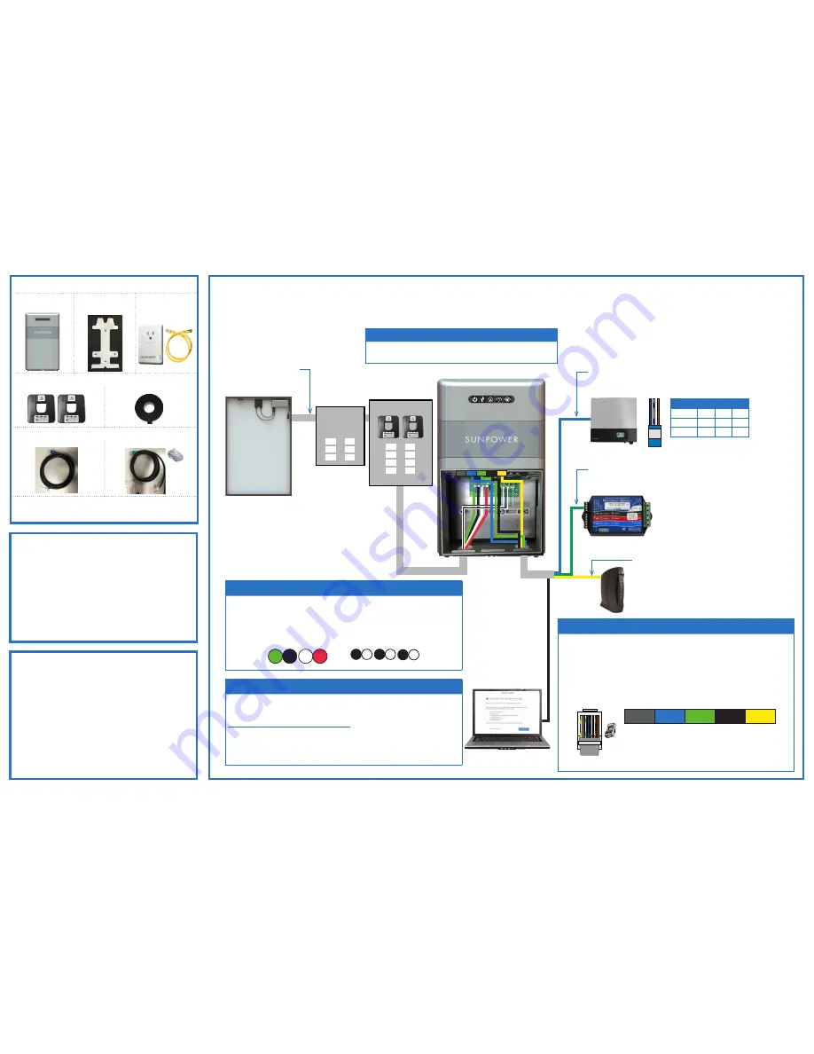
Connection Diagram
Refer to the
AC Module System
Design and Intall Guide
for
installation instructions.
AC Module Connection
See other side for detailed installation instructions.
Warning!
Do not power up the solar system until after you complete Steps 1 through 3.
Important!
Do not run communication cables through same opening or conduit as power wire.
Refer to the
PVS5x Devices Guide
for installation and wiring instructions
.
DC Inverter Communication
Connect the cable with the blue connector cable from the
RS-485
2-WIRE
port to the first inverter.
Refer to the
PVS5x Devices Guide
for installation and wiring instructions.
External Meter Communication
D+ D- GND
B b BR
Kit Contents
PV Supervisor 5x
(PVS5x)
Current Transformers (CTs)
Consumption CTs
(Optional) Production CT
Communication Cables
Inverters (blue connector)
External Meter (green connector)
Hardware
(2) M4 x 12 mm screws
(2) 3/4” sealing washers
(2) hole plugs
(4) 3/4” to 1/2” reducing washers
Connect the cable with the green connector cable from the
RS-485
2/4-WIRE
port to the meter communication terminals.
You Will Need
• Phillips screwdriver
•
Small flathead screwdriver
• RJ45 crimp tool
• Wire cutter
• Wire stripper
• Laptop with IE, Chrome, or Firefox installed
• Ethernet cable
• Your SunPower monitoring website credentials
• (Optional) Customer’s Wi-Fi network and password
Bracket
Connect Ethernet cable from router to WAN port, or connect
cable from Power Line Ethernet Adapter to router (with
supplied yellow in-home Ethernet Adapter cable), or connect to
homeowner’s Wi-Fi.
Internet Connection
1. Mount the PVS5x
Select location, mount bracket and secure with
appropriate hardware, and fit PVS5x onto bracket.
2. Wire the PVS5x Power
Remove PVS5x covers (external enclosure, internal AC wiring
top and bottom), place partition, run power conduit, run
240 VAC and land in terminals, run CT wires and land in J16,
replace AC wiring covers.
L1
GND
L2
N
W
B
W
B
W
B
CONS L1 CONS L2 PROD
240 VAC
CT Wiring
4. Use the PVS Management App to Commission
Turn laptop Wi-Fi off , connect Ethernet cable from laptop to
PVS5x
LAN1
(black) port, open a browser and type:
www.sunpowerconsole.com
Follow the instructions to setup communication, check
firmware, discover devices, verify device operation, and
commission the site.
3. Connect Communicaton
• Run communication conduit
• Install Ethernet cable, or Power Line Ethernet Adapter, or
connect to homeowner’s Wi-Fi
• Connect inverter communication to PVS5x (AC Modules
already connected through service panel)
• Connect cable from meter to open RS-485 port
• Replace the enclosure cover
o 0 g B b G br BR
T-568B
RJ-45 Plug
Clip is pointed
away from you
PVS5x
(all ports)
D-AUX
RS-485
2-Wire
LAN1
RS-485
2/4-Wire
WAN/
LAN2
SMA/ABB/METER/
OTHER (2-W)
INSTALLER
COMPUTER
FRONIUS (4-W)/
METER/OTHER
HOMEOWNER
ROUTER
Power Line
Ethernet Adapter
and Cable
Int
erne
t Communic
ation
Cellular Communic
ation
De
vice Communic
ation
Inv
ert
er Err
or
Po
we
r
AC
Module
Sub-Panel
Service Panel
2-Wire RS-485 Connections
Label
D+
D–
GND
SMA TB
2
7
5
ABB TB
4
5
3


