Main Breaker
Utility Meter
L2
L1
CT
CT
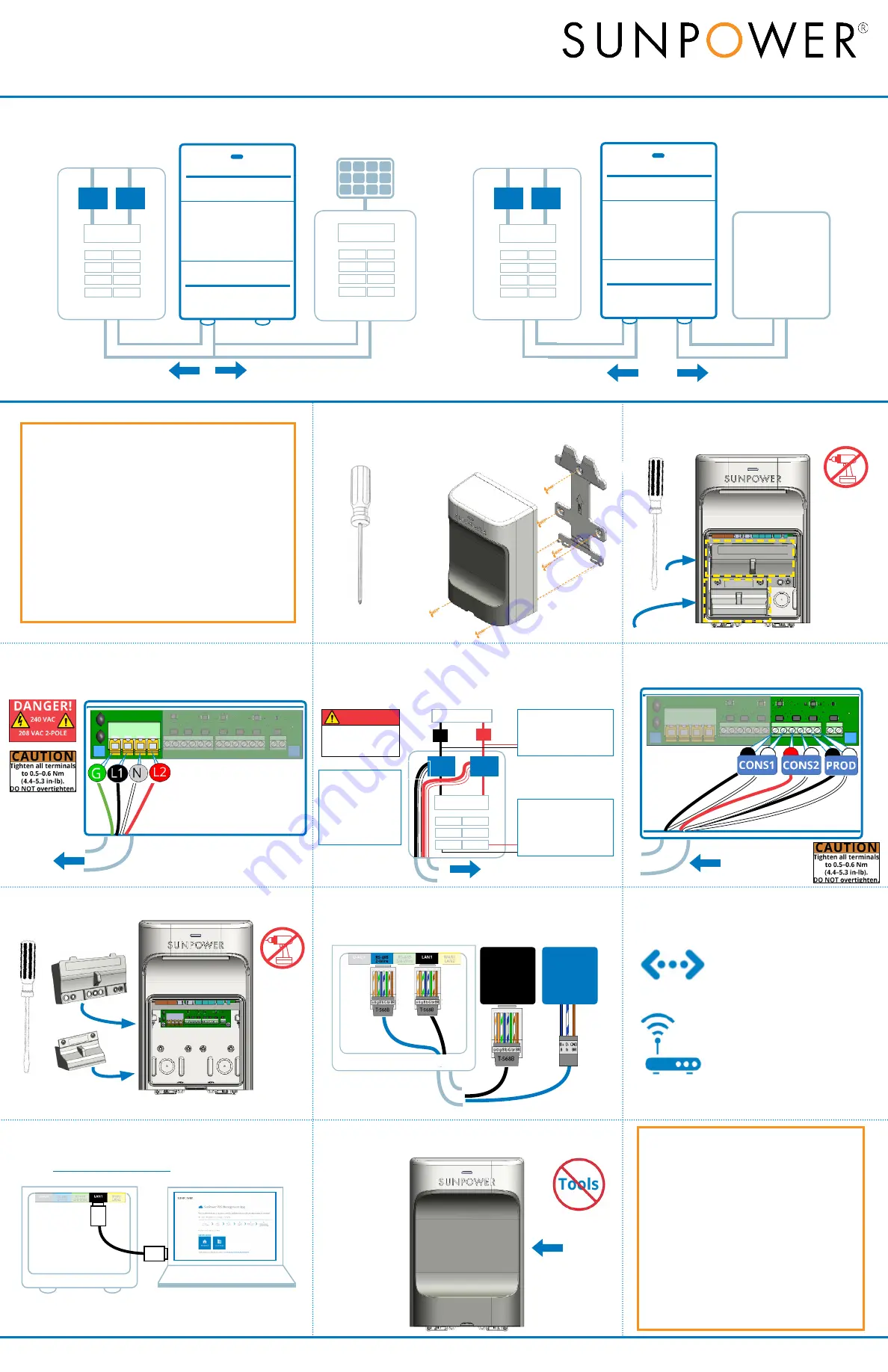
3. Wire PVS6 power
Use copper conductors only, with min. 75
°
C temp. rating.
Install a
dedicated 240 or 208 VAC circuit. Land wires in J2 terminals: green to
GND; black to L1; white to N; and red to L2.
4. Install consumption CTs
Refer to Section 3 on the other side for complete CT installation instructions.
Place CTs around incoming service conductors: L1 CT (black and white wires)
around Line 1 and L2 CT (red and white wires) around Line 2.
6. Replace PVS6 wiring covers
Use screwdriver to replace AC wiring covers over AC power wires.
5. Wire consumption CTs
Land wires in J3 terminals: L1 CT and L2 CT wires
to corresponding CONS L1 and CONS L2.
7. Connect DC inverter communication
If DC inverter is installed, connect communication from DC inverter to
the PVS6. No additional connection is required for AC modules.
Never run
communication cable and
AC wiring in same conduit
SMA US-40
Inverter
Port A or B
SMA US-22
Inverter
2
(B)
7
(b)
5
(BR)
10. Replace PVS6 cover
Snap the enclosure cover onto the PVS6.
8. Connect PVS6 to the internet
Connect to customer’s internet with either:
Customer’s Wi-Fi
Connect during commissioning
with network and password.
Ethernet Cable
From PVS
6
LAN2 to customer’s
router (recommended method).
9. Commission with PVS Management App
Turn off laptop Wi-Fi, connect Ethernet cable from PVS6 LAN1 to
laptop, open latest Chrome or Firefox, type
www.sunpowerconsole.com
, and follow instructions.
https://www.sunpowerconsole.com
PVS6 Quick Start Guide
Follow these instructions to install, configure, and commission the PV Supervisor
6 (PVS6) to begin receiving monitoring data.
Refer to the
PVS6 Installation
Instructions
on the other side for the complete instructions.
CT
CT
Main Service Panel
PVS6 Connection Diagram: DC Inverter Site
\
DC Inverter
Wire PVS6 power and CTs into
main service panel
Wire communication
from PVS6 to inverter
Wire PVS6 into AC
module subpanel
Wire CTs into main
service panel
AC Module Subpanel
CT
CT
Main Service Panel
PVS6 Connection Diagram: AC Module Site
AC Module Array
From CTs around
service conductors
Load-Side System:
Solar output
installed on breaker
in service panel or
downstream of CTs
.
Line-Side System:
Solar output
installed
on line-side tap or
upstream of CTs
.
To PVS6
To 15 A or 20 A
dual-pole breaker
Routing wire and cable:
• Fill all conduit openings in the enclosure with
components rated NEMA Type 4 or better
to maintain the integrity of the enclosure’s
environmental system.
•
Drill extra 0.875
”
(22 mm) or 1.11
”
(28 mm) conduit
openings, if required, with step drill (
do not
use
screwdriver or hammer).
•
Use only the provided conduit openings or drillout
locations and never cut holes in the top or sides of
the enclosure.
•
Never run inverter or Ethernet communication cable
in the same conduit as AC wiring.
•
CT and AC wiring may be run in the same conduit.
Note:
For sites with SMA US-40 DC inverter, connect Ethernet
cable from laptop to port A or B in the last (or only) inverter.
PVS6 Installation Instructions and Quick Start Guide
531566 RevA
Copyright 2018 SunPower Corporation
2 of 2
Hazardous voltage
Use appropriate PPE and
turn off power to the
service panel.
DANGER!
SUNPOWER
PVS6
SUNPOWER
PVS6
Remove lower cover first
2. Remove all PVS6 covers
Use flathead screwdriver to carefully remove the
enclosure cover. Use Phillips to remove the AC wiring
covers.
1. Mount the PVS6
Mount the PVS6 bracket to the wall using hardware that supports 6.8 kg
(15 lb); use Phillips screwdriver to secure the PVS6 to the
bracket using the two provided screws.
Use only UL
Listed, double-
insulated, XOBA
CTs with the
PVS6.
•
Always open or disconnect circuit from power-
distribution system (or service) of building before
installing or servicing current transformers (CTs).
•
The CTs may not be installed in equipment where they
exceed 75% of the wiring space of any cross-sectional
area within the equipment.
•
Restrict installation of CT in an area where it would
block ventilation openings.
•
Restrict installation of CT in an area of breaker arc
venting.
•
Not suitable for Class 2 wiring methods.
•
Not intended for connection to Class 2 equipment
•
Secure CT, and route conductors so that they do not
directly contact live terminals or bus.
•
WARNING!
To reduce the risk of electric shock, always
open or disconnect circuit from power-distribution
system (or service) of building before installing or
servicing CTs.
•
For use with UL Listed Energy Monitoring Current
Sensors rated for Double Insulation.
Warning!
To protect against risk of electrical shock reinstall
the AC wiring covers before reenergizing the equipment.


