6
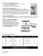
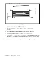
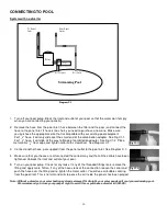
1 - Mounting kit (part # SQ-RMK5) is required
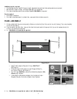
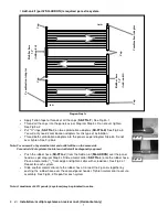
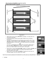
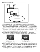
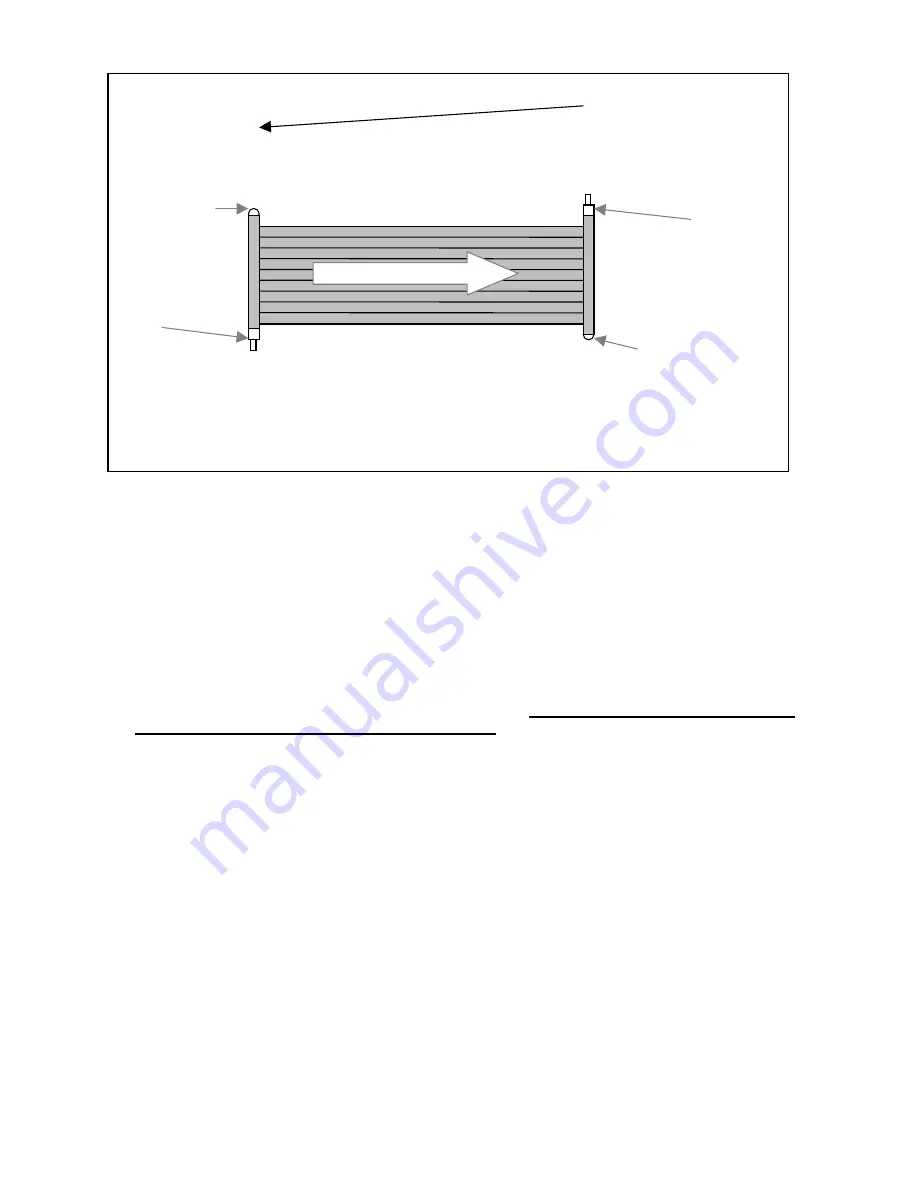
Diagram Step 3b
•
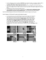
Apply Teflon on two of the caps (
SK-FTG-F
). See Fig 3a-1.
•
Thread the 2 caps into the panels as per Diagram Step 3b. Do not over tighten.
See Fig 3a-2
•
Put "O" rings (
SK-FTG-I
) on both combination adapters (
SK-FTG-D
). See Fig 3a-3
•
Thread both combination adapters into the panels as per Diagram Step 3b.
Do not over tighten. See Fig 3a-4
•
Install mounting kits as per instructions included with them.
Panels must be installed with a slight
slope (minimum 1 inch per 10 feet) toward the inlet
. This will allow the panel to drain properly.
Note: The inlet must always be at the lower end of the panel and the outlet at the higher end of the panel.
3. c)
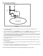
Installation: multiple systems on ground
.
A Minimum of 1 inch fall per 10 feet
C
o
m
b
in
a
ti
o
n
A
d
a
p
te
r
C
a
p
C
a
p
Inlet
Outlet
C
o
m
b
in
a
ti
o
n
A
d
a
p
te
r


