Figure 6
3
4
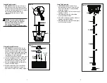
Lamp Post Assembly
1.
(SEE FIGURE 6)
Attach lower post (F) to
lamp post base (F) using 3 screws (L) if you
have not already done so in “Support Ring
Assembly” on page 3.
2. Attach the middle post (E) to the lower post (F)
turnimng clockwise.
3. Attach the upper post (D) to the middle
post (E), turning clockwise.
4. Attach the second upper post (D) to the first
upper post, turning clockwise.
5. Attach the lantern assembly (C) to the upper
post (D), turning clockwise.
Figure 4
Figure 5
Support Ring Assembly
1.
(SEE FIGURE 4)
Attach lower post (F) to post
base (G) using screws (K) in 3 places. Lower
the support ring (J) down the post until it rests
on the top of the upper planter (H). To complete
the solar lamp post with planter go to
"Lamp Post Assembly" steps 2, 3 and 4
on page 4.
Alternate Ground Mounting
1.
(SEE FIGURE 5)
Thread hex nut (N) onto the
J-bolt (Q). Make sure the hex nut is threaded
down the J-bolt far enough for the top of the
J-bolt to fit through the mounting plate (R) and
the lamp post base (G) with enough threads to
secure the base to the J-bolts with
acorn nuts (O). Repeat the step for other J-bolts.
2. Using the mounting plate (R) as a guide insert
the J-bolts with hex nuts into a wet concrete
pad until the hex nuts are below pad level.
3. Place the mounting plate (R) onto the J-bolts
forming a mounting bracket.
4. Align the lamp post base (G) holes with the
J-bolts and secure with the acorn nuts (O).
Note: Refer to "Lamp Post Assembly" on page 4.
J
F
H
Concrete
Pad
Level
O
G
N
Q
R
CAUTION:
To prevent product damage or
personal injury from tip-over, lamp post
planter base must be placed on a flat,
level surface and be filled with
4 in. (minimum of 40lbs.) of gravel or stone.
K
G
C
L
G
E
F
D
D


