background image

 4


Subject to change without notice. Information without guarantee. /  07.01.2021


Installation


Operation


• 

Approved wire diameter: AWG16—AWG20 / 0.5mm

2

-

1.5mm


AC PUSH


While connected with a AC PUSH, the digital display will show 

PD

” 

which means Push Dimmer Mode, ope-

rations under Push Dimmer Mode are as follows:


1. Click the button to switch ON/OFF


2. Press and hold down the button to increase or decrease light intensity to desired level and release it, 
then repeat the operation to adjust light intensity to opposite direction. The dimming range is from 1% to 
100%.


Set DALI address manually via buttons


1.


Press one of the two buttons until the LED display starts flashing. 


2.


Press one of the two buttons briefly to change the corresponding number until the desired number 
lights up. Use the left button to change the number by 10 units, the right button to change the num-
ber by 1 unit. The address can be set from 00

-

63.


3.


Then press one of the two buttons until the display stops flashing.


Information: The DALI address can be set manually from 00

-

63

-

FF. No DALI address is assigned in the 

factory setting. The display shows FF. If the unit is manually set to FF, it is reset to the factory setting. 


Assigning a DALI address via a DALI master


The DALI address can also be programmed automatically via a master. Please refer to the operating instruc-
tions of the respective DALI master. 


Information: The display will show AU if the DALI Master assigns the address to the device.


SAFETY AND WARNINGS 


• 

Do not install with power applied to the device 


• 

Do not set operation current with power applied to the device 


• 

Do not expose the device to moisture 


• 

Drivers with PWM dimming can cause noise due to vibrations. These can be generated by vibra-

ting components in the device as well as by resonant vibrations from other bodies.


Summary of Contents for SRP-2305-50-TW-CC

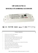
Page 1: ...0W Output current from 250mA to 1500mA selectable via DIP switches Class 2 power supply completely insulated plastic housing High power factor and efficiency Built in DALI interface DALI DT6 device the device can be controlled via 1 2 DALI address Colour control according to DALI DT6 specifications Complies with DALI IEC 62386 101 102 207 standard Generally compatible with DALI masters supporting ...

Page 2: ...ange 0 100 Dimming Methode PWM 1 5kHz Dimming Curve Logarithmic ENVIRONMENT Working Tempetrature 20 C 45 C Max Case Temperature 75 C Working Humidity 10 95 RH non condensing Storage Temperature 40 C 80 C Storage Humidity 10 95 RH IP Rating IP20 suitable for indoor LED lighting applications Safety EMC Safety Standards ENEC EN61347 1 EN61347 2 13 approved DALI Standards Comply with IEC 62386 101 102...

Page 3: ...3 Subject to change without notice Information without guarantee 07 01 2021 Product dimension Wiring diagram DALI AC PUSH ...

Page 4: ...e the number by 10 units the right button to change the num ber by 1 unit The address can be set from 00 63 3 Then press one of the two buttons until the display stops flashing Information The DALI address can be set manually from 00 63 FF No DALI address is assigned in the factory setting The display shows FF If the unit is manually set to FF it is reset to the factory setting Assigning a DALI ad...

Page 5: ...lp Situation A The power supply has been overloaded and is now in overload protection mode What does the error pattern look like The connected LEDs flash You can reduce the brightness via a DALI software and the strip will stop flashing You can no longer control the colours with the software How can the problem be solved two variants A B A 1 Disconnect the device from the mains for at least 10 min...

Reviews: