
R90
™
SHROUD REPLACEMENT
Sunrise Medical 2842 N. Business Park Ave Fresno, CA 93727 USA
© 2022 Sunrise Medical (US) LLC
07/2022 253772 Rev. A Page 2of2
Customer Service: +1(800) 333-4000
or visit www.SunriseMedical.com
™
™
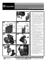
7. To remove the PCB (K) from the
right shroud, loosen the screw (L).
(Fig. 7)
Note: for reassembly, ensure screw
is aligned with PCB mounting hole.
8. Disconnect the connectors from
the top of the PCB (Fig. 8). Pull the
9-Pin connector from the motor
(Fig. 9) through the right shroud
before disconnecting. Ensure the
motor harness stays on the outside
until the PCB is reconnected.
9. Disconnect the connectors (I) from
the bottom of the PCB (Fig. 9) and
remove the battery plate (J)
(Fig. 7).
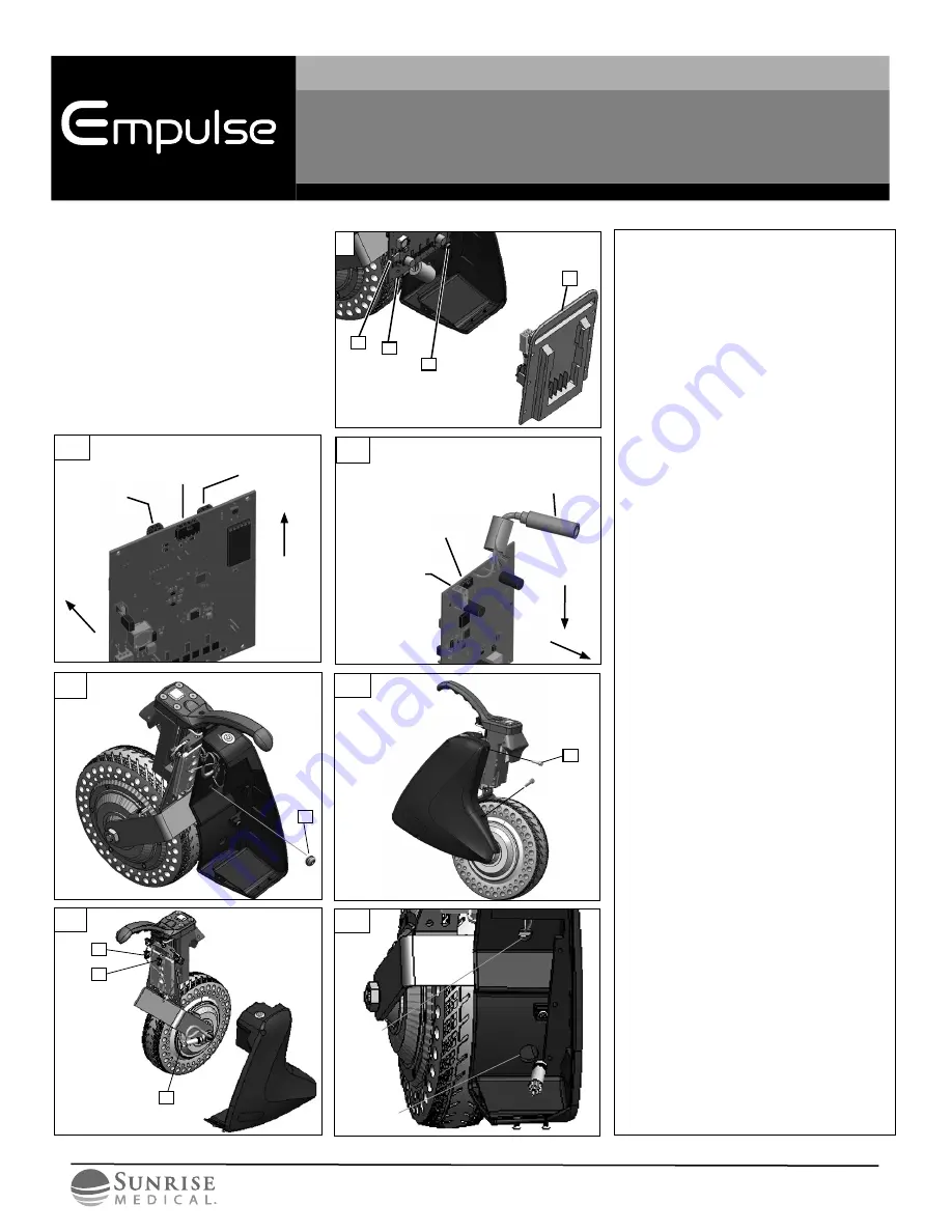
10. Remove the wire grommet (M) on
the shroud using a fl at head screw
driver. (Fig. 10)
11. To remove right shroud front
hardware, use a M4 Allen wrench
to remove socket head cap screws
(N). (Fig. 11)
12. To remove right shroud, pull the
harnesses for the motor (O), the
actuator (P), and switch (Q)
through the shroud. (Fig. 12)
13. Ensure you note the orientation of
the PCB shown in Fig. 8 and Fig. 9
before reinstalling the PCB.
Incorrect installation will result in
damage to the PCB. You will need
to connect the motor connector
from the PCB fi rst. Then, push the
motor connector back through the
hole in the right shroud.
14. Connect the motor connector from
the PCB fi rst. Push the motor
connector back through the hole in
the right shroud.
15. Connect the connectors on the
top of the PCB (Fig. 8). Connect the
connectors from the battery plate
(J) to the bottom of the PCB
(Fig. 9). Reconnect the connector
from the charger port (G) (Fig. 6) to
the battery plate (J) (Fig. 7).
16. Replace the right shroud by
following steps 10-12 in reverse.
17. Complete reassembly by following
steps 1-6 in reverse.
10
M
11
N
13
12
P
Q
O
Top hole:
actuator,
switch
harness
Bottom hole:
motor harness
8
4-Pin connector
from grommet in
right shroud
4-Pin connector
from Power button
in right shroud
Front of
R90
Top of
R90
2-Pin connector
from grommet in
right shroud
9
Front of
R90
Top of R90
2-Pin connector (
I
)
from battery
plate (J)
4-Pin connector (
I
)
from battery plate (J)
9-Pin connector
from motor
7
J
L
K
I
View from bottom of PCB


