J a y
®
F o c u s P o i n t B a c k
100823 Rev. A
4
5. Orient the clamp, so that the hook cradle faces the front of the wheelchair.
6. Tighten the screw using a 3/16” Allen wrench. Tighten the clamp just enough to
prevent it from sliding on the tube. Do not completely tighten until the correct
height location of the back is established (see instructions for height adjustment
on page 5).
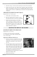
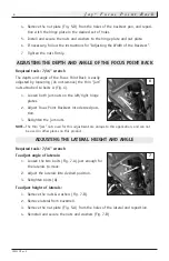
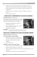
INSTALLING THE TOP DROP PIN CLAMP (Figure 2)
Required tools: 3/16” Allen wrench
1. Follow steps one through four above.
2. Orient the clamp as shown in figure 2, so that
the drop pin (E) faces the front of the wheelchair.
3. Tighten the screw (A) using a 3/16” Allen
wrench. Tighten the clamp just enough to pre-
vent it from sliding on the tube. Do not com-
pletely tighten until the correct height location
of the back is established (see instructions for
height adjustment on page 5).
ADJUSTING THE WIDTH OF THE BACKREST
ADJUSTING THE WIDTH OF THE HINGE PLATE
Required tools: 7/16” wrench.
The width of the hook brackets are adjustable
to accommodate various widths of backrest tubes
over a certain range.
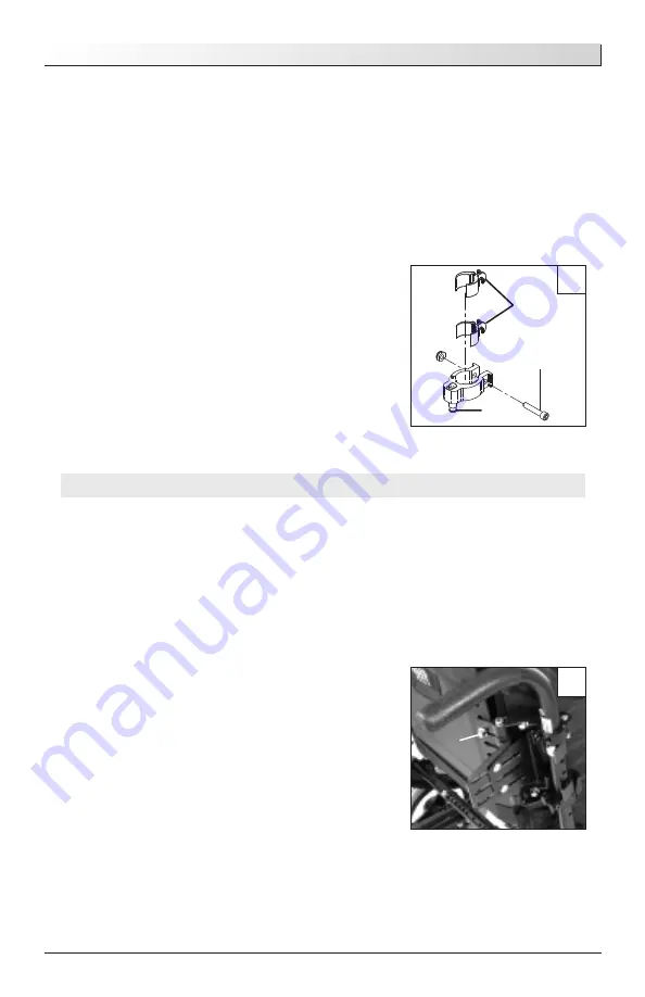
Adjusting for Wheelchair Width (Fig. 3)
1. Loosen the nuts (A) securing the left and right
hinge plates. The nuts should be loose enough
to allow the hinge plates to slide along the
back pan.
2. Place the backrest against the wheelchair back-
rest tubes. Slide the hinge plates inward or out-
ward so that the hooks will easily drop into the
cradle of the bottom post clamps. Make certain
that the position of the left and right hooks
with respect to the backrest pan are the
same (symmetrical), so that the pan is centered
between the backrest tubes.
3. Tighten the nuts firmly.
2
A
C
E
3
A


