background image

7

2  Issue 4

Using your chair

Centre of balance (continued)

2. Changing the setup of this chair

increases the risk of a fall or tip
over. Be very careful if you make
a change to any of the following:

!

 The position of the rear axles,

the distance between the rear
wheels or the amount of rear
wheel camber.

!

 The distance between the

centre of the front castors and
rear wheels and the angle of the
castors.

3. To avoid a fall or tip over you

should:

!

 Have someone help you until

you know the balance points of
your chair and how to avoid a tip
over.

!

 Use anti-tip tubes until you

are sure you are not at risk to tip
over.

4. The centre of balance and

stability of your chair are also
affected by:

!

 A shift in your body position,

posture or weight distribution.

!

 Riding your chair on a sloped

surface.

!

 Fitted seating systems.

Refer to the sections that follow to
learn how you can reduce the risk
of a fall or tip over by proper use of
this chair.

Dressing and changing
clothes

Warning:

Your weight may shift if you dress
or change clothes while seated in
this chair. This may cause a fall or
tip over and severe injury to you.
To help prevent this you should:

1. Rotate the front castors to the

forward position.

2. Lock anti-tip tubes in the down

position if your chair has anti-tip
tubes.

3. Back your chair up against a wall

and lock both rear wheels.

Summary of Contents for Quickie 2 range

Page 1: ...Owner s Manual 2 range ...

Page 2: ...51 2 Issue 4 ...

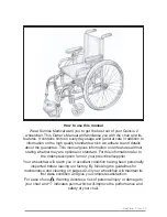
Page 3: ...s without stating whether they are optional or standard For this information refer to the order prescription form or your prescriber supplier Your wheelchair will reach you in excellent condition having been personally inspected before leaving our factory By following the guidelines for maintenance and cleaning on pages 42 43 your wheelchair will maintain its first class condition and give you com...

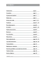
Page 4: ...17 19 Elevating legrests page 20 Armrests page 21 22 Quick release axles page 22 Backrest page 23 Push Handles page 24 Wheel locks page 25 Chair adjustments page 26 37 Lap belt instructions page 38 40 Transportation page 41 Maintenance schedule page 42 Cleaning guidelines accessories and tools page 43 Technical data page 44 Sunrise Medical page 45 ...

Page 5: ...quality management systems This approval ensures we provide quality in all areas of our business from development through to final delivery This product is manufactured to comply with the Medical Device Directive 93 42 EEC If you have any queries about the use maintenance or safety of your wheelchair please contact your wheelchair prescriber supplier Sunrise Medical will be pleased to answer any o...

Page 6: ...haser All Quickie wheelchairs parts and components including frame components axle plates castors armrest backrests etc are guaranteed against defects in materials and workmanship for one year from purchase date Warranty conditions 1 This warranty does not affect the statutory rights of the Customer but if the Customer wishes to have the benefit of the Company s warranty the Customer must comply w...

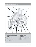
Page 7: ...11 12 1 Armrests height adjustable shown 2 Backrest 3 Pneumatic tyre 4 Aluminium handrim 5 Quick release axle 6 Adjustable axle plate 7 X spoked wheel 8 Wheel lock 9 Castor assembly 10 Swing away release catch 11 Flip up footrests 12 Seat cushion 2 10 ...

Page 8: ...attempt to go up or down inclines greater than 10 1 in 10 Anti tip tubes Under normal use anti tip tubes will prevent the wheelchair from tipping over backwards Anti tip tubes are available from your local wheelchair prescriber supplier Sunrise Medical recommends anti tip tubes for first time and less experienced wheelchair users Tyre pressure Ensure that pneumatic tyres are properly inflated The ...

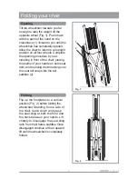
Page 9: ...ront of the chair placing the palms of your hands on both seat rails and pressing down making sure the seat rail snaps into the rail saddles 2 Fig 1 Fig 2 1 2 Folding Flip up the footplates to a vertical position Fig 2 before folding the wheelchair Standing to one side of the chair reach down and grasp the seat sling at both the front and the back between your hands Lift sharply to disengage the s...

Page 10: ...t suited to your abilities and those of the rider 3 Always use good posture and proper body mechanics When you lift or support the rider or chair bend your knees slightly and keep your back as upright and straight as you can 4 Unlock and rotate anti tip tubes up out of the way to avoid a trip or fall when operating the chair from the back 5 Always lock the rear wheels and lock anti tip tubes in th...

Page 11: ... you are sure you are not at risk to tip over 4 The centre of balance and stability of your chair are also affected by A shift in your body position posture or weight distribution Riding your chair on a sloped surface Fitted seating systems Refer to the sections that follow to learn how you can reduce the risk of a fall or tip over by proper use of this chair Dressing and changing clothes Warning ...

Page 12: ...learning to do a wheelie make sure that this chair has push handles The attendant needs secure points to hold the rear of the chair to prevent the user from tipping over backwards Follow these steps when learning to do a wheelie with help 1 The attendant should be at the rear of the chair and must be able to move with the chair to prevent a tip over 2 The attendant s hands should be beneath the pu...

Page 13: ...y cause the chair to tip forward do not lock the rear wheels This creates a tipping point and makes a fall or tip over more likely Doorways and obstacles Warning 1 As much as possible ensure that the floor areas where you use the chair are level and free of obstacles by removing or covering threshold strips between rooms installing a ramp at entry or exit doors 2 If your chair has anti tip tubes m...

Page 14: ... as you can 3 Be very careful if you must climb a slope greater than 10 1 in 10 Ask for help if the slope may be beyond your ability On a steep slope anti tip tubes may not prevent a tip over On a steep slope you may not be able to reach the top without stopping If you have to stop turn the chair sideways on to the hill otherwise you may lose control and tip over 4 Always control your speed when g...

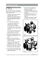
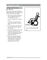
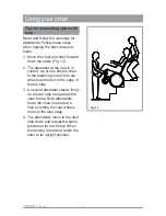
Page 15: ...can perform safe transfers on your own 3 Wherever possible position your wheelchair as illustrated in Fig 5 and 6 4 Always lock the rear wheels before you transfer to keep the chair from rolling Locking the rear wheels will not always keep your chair from sliding away from you or tipping 5 Rotate the front castors forward to make the chair more stable 6 If your chair has armrests make sure that th...

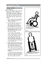
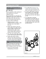
Page 16: ... do a wheelie and you are sure you have the upper body strength needed to do so 2 Unlock and rotate anti tip tubes up out of the way so they do not interfere 3 Do not try to climb a kerb or step more than 100mm 4 high unless you have help your chair may exceed its balance point and tip over Fig 7 4 When you have an attendant make sure that the chair has push handles The attendant must have secure ...

Page 17: ...erb or step turn the chair around and pull it backwards 4 While looking over your shoulder carefully step back until you are off the kerb or step and standing on the lower level 5 Pull the chair towards you until the rear wheels reach the edge of the kerb or step Then allow the rear wheels to slowly roll down onto the lower level Fig 9 6 When the rear wheels are safely on the lower level tilt the ...

Page 18: ... 2 Face the kerb and tilt the chair up on the rear wheels so that the front castors clear the kerb or step Fig 10 3 Move forward placing the front castors on the upper level as soon as you are sure that they are past the edge 4 Continue forward until the rear wheels contact the face of the kerb or step Fig 11 Lift and roll the rear wheels to the upper level Fig 11 Fig 10 100mm 4 MAXIMUM KERB HEIGH...

Page 19: ...nd rider 3 Use only non detachable parts of the main frame as hand holds 4 Make sure that the rider is secure in the chair with his or her feet arms and hands safely out of the way of any obstacles Tips for climbing stairs with help Read and follow the warnings for attendants Follow these steps when helping the rider climb stairs 1 Move the chair and rider backwards up the stairs 2 The attendant a...

Page 20: ...he tilts the chair to the balance point of the rear wheels and rolls it to the edge of the top step 3 A second attendant stands firmly on a lower step and grasps the chair frame Both attendants lower the chair one step at a time by letting the rear wheels roll over the step edge 4 The attendants move to the next step down and repeat the same procedure for each step When the landing is reached retu...

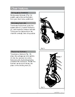
Page 21: ...e latch 1 toward the frame 2 and rotate the footrest outward To remove the footrest from the chair lift vertically from this position 1 3 4 5 2 2 Fig 14 Fig 15 Replacing footrests To replace a footrest Fig 15 place the swingaway pivot saddle 3 into the receiver 4 on the frame 2 with the footrest facing outward from the frame Rotate the footrest inward until it locks into place on the locking stud ...

Page 22: ...atch 1 toward the frame 2 and rotate the footrest outward To remove the footrest from the chair lift vertically from this position Replacing footrests To replace the footrest Fig 17 place the swing away pivot saddle 3 into the receiver 4 on the frame 2 with the footrest facing outward from the frame Rotate the footrest inward until it locks into place on the locking stud 5 1 2 3 4 2 5 ...

Page 23: ...19 2 Issue 4 Fixed flip up footrest Fig 18 shows the flip up footplate and Fig 19 the one piece flip up footplate Fig 18 Fig 19 Chair features ...

Page 24: ...n place Fig 20 Warning Pressure and leg weight must be off the ELR before positioning While making adjustment either hold leg remove leg from legrest or ask for assistance Articulating elevating legrests To fit or remove articulating legrests see instructions for swing away legrests To raise the legrest 2 lift to the desired position where it will automatically lock into place To lower the legrest...

Page 25: ...r to the first stop and remove the armrest Fig 22C To replace the armrest slide the armrest back into the receiver and return the release lever to locked position Fig 22 The armrest can be adjusted to remove free play in the receiver and inner arm post Fig 22 To tighten or loosen the fit of the outer post in the receiver first loosen the four 10mm A F bolts 5 two on each side of the receiver With ...

Page 26: ...way from the chair 1 2 Fig 23 Quick release axles To remove quick release axles Fig 24 simply press the quick release button 1 which is located in the wheel hub 2 and grip the wheel through the spokes 3 around the hub and pull the axle out of its sleeve 4 To replace slide the axle into the sleeve until the release button pops out and the two locking pins 5 are visible on the inside 6 of the sleeve...

Page 27: ...stery comes with front and rear insert slots The rear slot with no opening accommodates a standard back The front slot with top opening is used for push handle backs Optima backrest and upholstery Optima backrest upholstery is shown in Fig 26 Adjustable Velcro straps allow the backrest to be shaped to follow the exact profile of your back Fig 26 ...

Page 28: ...ush handles to the required position and re tighten the knobs Fig 27 Fig 28 Stabiliser bar To provide these chairs with additional rigidity a stabiliser bar 1 is also supplied Fig 28 To remove the bar prior to folding the chair the levers 2 need to be depressed on both sides of the bar whilst keeping the levers depressed the bar can be removed by pulling it backwards ...

Page 29: ...locks Fig 30 are mounted on clamping systems 1 and are correctly set prior to leaving the factory To apply the wheel lock pull the operating lever 2 forwards until you feel it go over centre and the grip arm 3 grips the tyre 4 Scissor locks can also be mounted on the lower frame tubes Fig 30B When mounted in the lower position the left hand lock must be mounted on top of the right hand frame and v...

Page 30: ...orque using a 4mm Allen key Chair adjustments 1 Fig 31 Fig 32 1 2 Footplate angle adjustment 90o adjustable flip up footplate To adjust the height of this type of footplate Fig 32 unscrew and remove the retaining screw 1 nut 2 and saddle washer 3 as shown move the footplate to the desired height and replace the retaining screw 1 saddle washer 3 and nut 2 and tighten to 8 10 Nm torque Use a 4mm All...

Page 31: ...ws 1 moving the footplate 2 forwards or backwards and aligning the holes in the footplate with the holes in the receiver 3 Replace the screws and tighten as above Adjusting Optima upholstery To adjust the upholstery first lift up the back flap 1 covering the strips with the user sitting in the chair proceed to loosen or tighten each individual strap 2 Fig 34 It is necessary to follow the profile o...

Page 32: ... and tighten to 5Nm torque setting Fig 35 1 2 Fig 36 Adjusting the angle of Optima backrests To adjust the angle of Optima backrests Fig 36 remove screw 1 and nut 2 and adjusting washer 3 Use a 4mm Allen key and a 10mm A F spanner Loosen screw 4 sufficiently to allow brackets 5 6 to rotate Turn the adjusting washer round to the desired angle and replace it into the recess 7 with all the holes in l...

Page 33: ...f 15Nm Some adjustments to the wheel lock position can be accomplished without moving the clamp To adjust loosen the two screws as above Slide the mounting bar 5 forward or backwards and rotate it to the correct angle position The grip bar should embed into the tyre approximately 4mm 3 16 when in the locked position Tighten the screws to a torque setting of 15Nm Warning Wheel locks when properly a...

Page 34: ...ng screws turn at a time to a torque setting of 15Nm Fig 38 5 Centre of gravity The centre of gravity Fig 39 is adjusted by moving the axle sleeve 1 backward or forward on the indexed axle plate 2 To move the axle sleeve undo the outer 28mm A F retaining nut 3 sufficiently to allow the locking washer 4 and the axle sleeve assembly to slide in the axle plate find the desired index slot 5 and tighte...

Page 35: ...etting on each side to ensure that the chair is level Note After changing the seat height always check Toe in toe out Fig 43 page 32 Angle of castors Fig 46 page 34 Both axles are in identical positions Wheelbase width The wheelbase width is adjusted by loosening the inner 1 and outer 28mm A F axle sleeve nuts 2 using adjustable spanners and positioning the axle sleeve 3 where required The nuts mu...

Page 36: ...oe in or toe out The toe in is set at the factory Should you require more toe in or toe out Fig 43B increase or decrease the number of washers 1 at the front or rear of the axle plate 2 More washers at the front decreases toe in and increases toe out More washers at the rear increases toe in and decreases toe out Remove the four 10mm A F axle plate nuts 3 and bolts 4 add or remove washers as requi...

Page 37: ...rotation of the castor fork 4 assembly Replace the dust cover 1 3 2 4 4 5 3 1 2 Seat height adjustment Two hole castor forks Fig 45 allow you to interchange 125mm 5 150mm 6 and 200mm 8 castor wheels and to adjust the seat height To adjust remove the axle bolt 1 and nut 2 with a 13mm A F spanner and remove the castor wheel 3 Either change the castor wheel size and or position the castor wheel upwar...

Page 38: ...stor housing 5 This will align the castor stem rotational axis perpendicular to the flat surface Rotate the bolts independently until they fall into position When the alignment is satisfactory re tighten the two retaining bolts Repeat the process for the other castor Recommended torque setting 8 10 Nm Fig 46 Castor reversibility The castor plate is generally mounted in a forward facing position 1 ...

Page 39: ...y snapping it back in place Fixed front frame Seat height adjustment Two hole castor forks allow you to interchange 125mm 5 150mm 6 and 200mm 8 castor wheels and to adjust the seat height Fig 49 To adjust remove the axle bolt 1 and nut 2 with 13mm A F spanners and remove the castor wheel 3 Either change the castor wheel size and or position the castor wheel upward or downward in the desired pre dr...

Page 40: ...ve castor assemblies from frame noting right positioned castor and left positioned castor Inside mount right castor on the left side and inside mount the left castor on the right side Forward or backward placement Loosen the two eccentric bolts 1 Remove the clevis pin 2 by taking off the locking spring 3 Slide the castor housing 4 forward or rearward and insert clevis pin into one of three pre dri...

Page 41: ...the Velcro to bring the sling to its correct tension Replace the screws and tighten to 5 8Nm torque Fig 52 1 2 Chair adjustments Fig 52 Fig 53 1 3 2 4 5 Backrest height To adjust the backrest height first remove the upholstery 6 10mm A F backrest nuts 1 bolts 2 and upholstery tabs 3 on the rear frame tubes 4 Slide the backrest tubes 5 to the desired height Replace the bolt upholstery tab and nut F...

Page 42: ...rough the tri glide Repeat on both ends of positioning belt Step 3 To fit the positioning belt to the chair Take the positioning belt strap and wrap around back post Step 4 Thread the positioning belt back through the tri glide to form a loop around the back post Thread positioning strap through tri glide as shown in step 5 Note Lap belts are fitted as positional aids and are not suitable as trans...

Page 43: ...itioning belt Step 6 To adjust the positioning belt use the tri glide buckles and the fastening buckle Fastening buckle Tri glides Step 5 Step 6 Step 7 Step 8 Step 7 Generally the Lab Belt should be fixed so that the straps sit at an angle of approximately 45 and when corretly adjusted should not allow user to slip down in the seat Step 8 When fastened check space between belt and user when correc...

Page 44: ...e adjusted correctly see step 7 and are free from any obstruction or adverse wear Sunrise Medical does not encourage the transportation of any person in a vehicle using this positioning belt as a method of restraint Please see Sunrise Medical transit booklet for further advice on transportation Maintenance Check lap belt and securing components at regular intervals for any sign of frays or damage ...

Page 45: ...ements of ISO 7176 19 6 The wheelchair must be secured by a 4 point Tie Down Restraint system conforming to ISO 10542 part 2 7 The occupant must be restrained independently of the wheelchair by a lap and diagonal safety belt conforming to ISO 10542 part 3 Sunrise Medical postural lap belts are for postural support only and not suitable as restraints during transportation 8 Any detachable accessori...

Page 46: ...straight line with no excess drag or pull 6 Folding of the backrest Check the backrest folds and opens smoothly Check for loose fasteners 7 Armrests swing away Check that all fasteners are secure and that all mechanisms work freely 5 Seat sling and back uphostery Check for wear or sagginess in the upholstery 8 Complete inspection safety check and service should be made by an authorised Sunrise Med...

Page 47: ...brasive cleaner followed by polishing with a non abrasive automotive wax Cleaning guidelines accessories and tools Accessories Anti tip tubes Backpack Caddy Crutch holder Leg strap Positioning belts Long Velcro style 170cm 67 Short Velcro style 145cm 57 Long buckle 163cm 64 Short buckle 137cm 54 Seat pouch Spoke guard clear Spoke guard black Step tube left Step tube right Swing away tray table Too...

Page 48: ...5 5O min 11 5O max Static stability sideways 19 5O min 23O max Seat plane angle 7 4O Effective seat depth 420mm Effective seat width451mm Seat surface height at front edge 444mm Backrest angle 10O min 25O max Backrest height 415mm Footrest to seat distance 345mm min 467mm max Leg to seat surface angle 106O Armrest to seat distance 304mm min 427mm max Front location of armrest structure 244mm Handr...

Page 49: ...enuinely caring for our customers We pride ourselves not only on designing and building the most innovative products but also on our commitment to offer an excellent standard of customer service both during and after sale In addition to your new Quickie 2 Sunrise also manufacture oxygen concentrators nebulizers and hoists We have a vast range of aids to daily living which include the Merlin Bath L...

Page 50: ......

Page 51: ...Sunrise Medical Limited High Street Wollaston West Midlands DY8 4PS England Tel 44 0 1384 44 66 88 Fax 44 0 1384 44 66 99 www sunrisemedical co uk ...

Reviews: