background image

930466 Rev. A

X .   O p e r a t i n g   G u i d e

41

5. Joystick (E)

The joystick controls the direction and speed of your chair. Turn the chair on and move
the joystick in the direction you want to go.

• Moving the joystick from the neutral (center) position disengages the motor

locks, allowing the chair to move. 

• The chair will move faster the more you move the joystick away from neutral. 

NOTE–

If your speed becomes hard to manage, release the Joystick and the chair will
come to a complete stop.

• When you release the joystick it will return to neutral; the chair will slow to a

stop and the motor locks will reengage.

• We recommend that you switch the chair off if you stop for any length of time.

This will conserve battery power.

NOTE–

Once the chair stops, switching the chair off will not affect the motor locks. 

6. Joystick Boot (F)

Make sure the boot is not torn or cracked (this could allow debris, water or moisture
to enter). If the boot is torn or cracked, replace it as soon as you can.

7. Remote Switch Jacks (optional) (I)

Two 1/8" switch jacks are optional to provide remote switch control of the on/off
power function and the mode select function.  Any of the single switches offered by
Sunrise Medical can be used to connect to either or both of these jacks (except the
single zero touch switch).

1. Never use the ON/OFF switch to stop your chair except in an emergency. 

This will result in an abrupt stop, and may cause you to fall.

2. To slow or stop your chair, return the joystick to neutral.

X .   O p e r a t i n g   G u i d e

930466 Rev. A

40

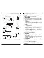
E. JOYSTICK ASSEMBLY

The joystick connects to a controller, which controls
the chair’s performance. The joystick assembly consists
of the following parts: 

1. Speed Control Knob (A) 

Use the speed control knob to adjust the maximum
speed of your chair. Turn it counter-clockwise to reduce
speed; turn it clockwise to increase speed.

2. Battery Charge Indicator (B)

• Green lights indicate that batteries are fully

charged. 

• Yellow lights indicate that batteries need

recharging. 

• When the lights stay in the red band, the batter-

ies must be recharged.

3. On/Off Mode switch (D)

The on/off mode switch is located on the rear face of
the joystick housing. It is a toggle switch. Turning the
chair on or off, is accomplished by pressing the switch
downward. The switch will automatically return to the
center point. Alternate locations exist for this switch.
Please see your supplier in the event that you wish to
relocate or re-orient this switch.

4. Mode Switch (D)

The on/off mode switch allows you to select from 5
(five) different programmable drive profiles or actuator
mode sets.

• Push up the on/off mode select toggle switch to

index among the five drive and actuator modes.
The selected mode indicator will flash.

• Push joystick either left or right to select one of

the five drive profiles. To select the actuator
modes, push the mode select switch twice.

• The drive profiles are indicated by the mode indi-

cators (G) and the actuators are indicated by the
four actuator lights (H).

• To exit drive or actuator mode select, simply push

the on/off/mode toggle up one or more times
until the indicator no longer flashes, or push the
joystick forward or reverse to begin driving.

A

D

E

F

G

H

B

Remote Joystick

I

Summary of Contents for Quickie P-222

Page 1: ...uickie P 222 User Instruction Manual Warranty Supplier This manual must be given to the rider of this wheelchair Rider Before using this wheelchair read this entire manual and save for future referenc...

Page 2: ...mation about safety new products and options to increase your use and enjoyment of this wheelchair If you lose your war ranty card call or write and we will gladly send you a new one FOR ANSWERS TO YO...

Page 3: ...Chart 51 XIII WIRING DIAGRAM 52 XIV SUNRISE LIMITED WARRANTY 53 I I T a b l e o f C o n t e n t s 930466 Rev A 4 I INTRODUCTION 3 II TABLE OF CONTENTS 4 III YOUR CHAIR AND ITS PARTS 6 IV NOTICE READ...

Page 4: ...ustable footplate extended toe loops extension tubes solid one piece two piece locking Casters Standard 8 200mm pneumatic Option 8 200mm airless insert 8 200mm suspension 9 225mm pneumatic 9 225mm air...

Page 5: ...IR SAFETY OPTIONS Sunrise provides a choice of many power wheelchair styles sizes and adjustments to meet the needs of the rider However final selection of a wheelchair rests solely with you and your...

Page 6: ...broad types 1 Hand Held Transceivers The antenna is usually mounted directly on the unit These include Citizens band CB radios Walkie talkies Security fire and police radios Cellular phones Lap top c...

Page 7: ...ngs in this section If you fail to do so a fall tip over or loss of control may occur and cause severe injury to your or others A NOTICE TO RIDER 1 Before using this chair you should be trained in its...

Page 8: ...s authorized by Sunrise Doing so will void the Warranty and may create a safety hazard 1 If you modify or adjust this chair it may increase the risk of a fall or tip over 2 Modifications unauthorized...

Page 9: ...BALANCE The point where this chair will tip forward back or to the side depends on its center of balance and stability The Center Of Balance Is Affected By 1 The seat height and seat angle 2 A change...

Page 10: ...e very dangerous Even a small change in height may stop a caster wheel and cause your chair to tip You may need to Remove or cover threshold strips between rooms Install a ramp at entry or exit doors...

Page 11: ...r design will vary depending on such things as the length and height of the ramp the need for an intermediate platform landing size doors and the direction of swing and whether the ramp includes a tur...

Page 12: ...hat the person pushing the chair has full control when motor locks are disengaged H ON OFF SWITCH 1 Never use the ON OFF switch to stop the chair except in an emergency This will result in an abrupt s...

Page 13: ...air easier to use 1 Do not use this chair if any of the tires are under or over inflated Check weekly for proper inflation level as listed on the tire sidewall 2 Low pressure in a tire may cause the c...

Page 14: ...arnings in this Manual for that task 2 The Tips that follow are suggestions only Be aware that you will need to learn safe methods best suited to the rider and to your abilities Consult your health ca...

Page 15: ...move it using the battery straps Batteries may weigh up to 55 lbs 25 kg Care must be taken to avoid injury when lifting I X S e t U p A d j u s t m e n t U s e 930466 Rev A 28 TOOLS YOU WILL NEED 1 Ba...

Page 16: ...you achieve the desired joystick height Four posi tions are available by relocating the mount either on the top or bottom of the mounting bar D and or by rotation of the angle bracket mount I X S e t...

Page 17: ...in a forward or retracted position Adjustment a To retract joystick depress lever E located on side of armrest b Push joystick away from front of armrest until it locks into retracted position c To r...

Page 18: ...red angle There are five holes in 4 increments to choose from d Reinstall the front bolt and tighten both bolts securely L 12 DRIVE WHEEL Drive Wheel Position Adjustment a Remove the seat and main fra...

Page 19: ...it into the axle sleeve until it locks E ANTI TIP TUBES Sunrise Designs recommends anti tip tubes for all wheelchairs NOTE Use a torque setting of 100 in lbs when set ting up anti tip receivers 1 Ins...

Page 20: ...on A A few minutes wait is required before the circuit breaker will reset 2 Repeated Shutdown If the chair continues to shut down after resetting have it serviced by a supplier X O p e r a t i n g G u...

Page 21: ...u i d e 930466 Rev A 40 E JOYSTICK ASSEMBLY The joystick connects to a controller which controls the chair s performance The joystick assembly consists of the following parts 1 Speed Control Knob A U...

Page 22: ...ischarged Batteries Never allow a battery to completely discharge If you operate your wheelchair until it has almost stopped you will greatly reduce the life of your batteries Never let a battery sit...

Page 23: ...I B a t t e r i e s 930466 Rev A 44 B BATTERY CHARGER A battery charger produces a direct current DC When applied to a discharged battery this reverses the chemical reaction that led to its discharge...

Page 24: ...lid on power base and secure using the two 2 quarter turn fasteners push down on fasteners Never make direct contact across both battery terminals as an explosion may occur A spark may result in an e...

Page 25: ...maintenance will improve performance and extend the useful life of your chair 2 Clean your chair regularly This will help you find loose or worn parts and will make your chair easier to use 3 To prot...

Page 26: ...volume and may cause tire to burst 1 Check for signs of wear and correct air pressure in pneumatic tires weekly 2 For best performance inflate tires to the same pressure level as shown on the tire sid...

Page 27: ...This warranty is void if the original chair serial number tag is removed or altered c This warranty applies in the USA only Check with your supplier to find out if international warranties apply 4 WHA...

Page 28: ...N o t e s 930466 Rev A 54...

Page 29: ...Sunrise Medical Mobility Products Division 7477 East Dry Creek Parkway Longmont Colorado 80503 USA 800 333 4000 In Canada 800 263 3390 2000 Sunrise Medical 11 00 930466 Rev A...

Reviews: