background image

EN

GLISH

Q100R-Q200R Configured   Rev. A     

17

x5

x5

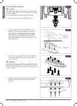
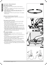
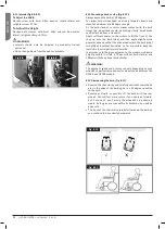
Fig. 5.15

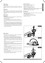
Fig. 5.16

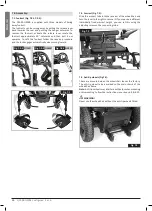
Fig. 5.17

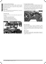
Fig. 5.18

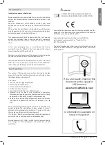
5.  Mark where to cut the screws. (Fig. 5.15).

6.  Remove the screws together with the spacer/spacers (Fig. 5.16).

7.  Cut the screw where the mark is (Fig. 5.17).  

It is very important that the fitter checks that the length of the 

bolts are correct. If bolts are too short to reach through all the 

threads - they will not have the strength to carry the loads 

required. If bolts are too long the batteries or other wheel chair 

components can be damaged. If necessary replace with longer 

bolts, or shorten them.

8.  Apply Loctite 222 (or an equivalent product) onto the screw 

(Fig. 5.18).

Summary of Contents for Quickie Q100 R

Page 1: ...000691020 UK Powered Wheelchair General Manual Q100R Configured Q200R Configured...

Page 2: ...have been awarded the ISO 13485 certificate which affirms the quality of our products at every stage from R D to production This products meet the requirements in accordance with EC guidelines Option...

Page 3: ...k or have limited mobility e g because of Paralysis Loss of extremity leg amputation Extremity defect deformity Joint contractures joint injuries Strokes and brain injuries Neurological disabilities e...

Page 4: ...icity and wide range of adjustments the Quickie Q100R Q200R is a perfect choice for easy service refurbishment and recycle requirements As a part of our ongoing product improvement initiative Sunrise...

Page 5: ...dicator 38 11 3 Locking unlocking the wheelchair 38 11 4 Operating the control joystick 39 11 5 Maximum speed profile indicator 39 11 6 The horn button 39 11 7 Speed Profile decrease button 39 11 8 Sp...

Page 6: ...lity to control the vehicle safely on a maximum slope see section 18 0 Specification Sheet section for maximum slope details If you are in any doubt as to the suitability of the power chair contact yo...

Page 7: ...not been maintained or serviced in accordance with the manufacturer s recommendations as shown in the user instructions and or the service instructions d Accessories have been used which are not speci...

Page 8: ...user of Potential Risk of serious injury or death if the advice is not followed WARNING Advice to the user of a potential risk of injury if the advice is not followed CAUTION Advice to user that poten...

Page 9: ...O NOT TOUCH HOT RED BLACK RED RED Controller connector YELLOW Battery connector Battery wiring schematic BLACK BLACK Battery connector BATTERY LABEL UNDER COVER CIRCUIT DIAGRAM TRANSIT TIE DOWN POSITI...

Page 10: ...dealer WARNING CHOKING HAZARD This mobility aid uses small parts which under certain circumstances may present a choking hazard to young children DANGER 4 3 Preliminary checks You should not try to m...

Page 11: ...auses an error message to appear in the control which is indicated when the LED display flashes rapidly For safety reasons the wheelchair can no longer be moved using the joystick Do not operate the f...

Page 12: ...ar access to attach tighten and release the wheelchair and occupant tie down restraints and safety belts Ease of access to and manoeuvrability in motor vehicles can be significantly affected by wheelc...

Page 13: ...ecured onto any accessories wishbones armrests anti tip brackets etc No changes or replacements must be made to the anchorage points car fastenings on the wheelchair or to constructional elements or p...

Page 14: ...mmends that the user transfers to the vehicle seating and uses the vehicle installed restraint system wherever possible Sunrise Medical recognizes that it is not always practical for the user to be tr...

Page 15: ...ted by wheelchair components during a crash Passenger with a user weight 22 kg When the user being transported is a child less than 22 kg mass and the vehicle involved has less than eight 8 seated pas...

Page 16: ...in picture Fig 5 13 WARNING Do not use any other screws than those supplied from Dahl engineering Part 502800 which is Quality 14 9 with Torx Key Size 27 Standard screws will not be strong enough in...

Page 17: ...Fig 5 17 It is very important that the fitter checks that the length of the bolts are correct If bolts are too short to reach through all the threads they will not have the strength to carry the load...

Page 18: ...t to buckle up for driving Release from the docking station 1 When the vehicle has been brought to a halt remove the safety belt 2 To unlock commence by driving the wheelchair forward to release press...

Page 19: ...ecial requirements instructions We advise you to check the following Is there a suitable and intended wheelchair area in the train for wheelchair users with adequate turning space to manoeuvre Is ther...

Page 20: ...arts are secured with your mobility aid or separately packed and labelled so they do not get lost during loading and unloading Take this user manual with you The carrier will need to refer to the foll...

Page 21: ...nation such as fluff hair etc is removed from the Velcro straps Such contamination may affect adhesion WARNING If you are in any doubt about the performance requirements of your wheelchair contact you...

Page 22: ...ber that the last thing a car or lorry driver expects to see is a wheelchair backing off the kerb into the road If in any doubt do not risk crossing the road until you are certain that it is safe Alwa...

Page 23: ...n forward when driving uphill with the seat and back in an upright position Alternatively sit in an upright position when travelling in a forward downhill direction or recline the seat backwards We st...

Page 24: ...fixed so that the straps sit at an angle of approximately 45 Fig 6 4 and when correctly adjusted should not allow user to slip down in the seat Place the strap loosely across the seat with the openin...

Page 25: ...over any chair malfunction take it to be repaired or reset Your dealer can help you to find the fault and correct it Make sure batteries are charged Do not use the chair when battery is low The chair...

Page 26: ...ng inward Q100R Q200R Q200R Fig 7 0 1 Fig 7 0 2 Fig 7 0 3 Fig 7 1 7 2 Armrest Fig 7 2 Slide the armrest tube into the receiver of the wheelchair and turn the lever to the right to secure it If you req...

Page 27: ...ee section 13 0 for details To disconnect the batteries Remove the front Battery cover by lifting upwards at the handle provided at the front of the cover Undo the two GREY plugs that connects the two...

Page 28: ...ators Fig 7 9 7 10 Where fitted ensure that the lights and indicators are functioning correctly and lens are clean before going outdoors at night Lights assemblies can become very hot Care must be tak...

Page 29: ...1 Fig 8 1 2 8 3 To use the wheelchair again Reverse the above procedure ie Put the cushion kerb climber backrest foot rests back in place Refit the batteries WARNING Never lift the wheelchair by the...

Page 30: ...36 psi 2 5 bars while for the rear wheels it is 40 psi 2 7 bars WARNING Never inflate the tyres with a service station air pump It is recommended that you use a manual pump or a pressure regulator man...

Page 31: ...ig 8 6 The following instructions explain how to manoeuvre correctly on steep ramps and slopes especially in the course of descent WARNING If your chair has a powered seat tilt powered recline or manu...

Page 32: ...then apply slightly more power and speed so that the drive wheels climb the kerb step smoothly and without hesitation As far as possible keep the joystick in the straight forward position In accordanc...

Page 33: ...his seating system in the reclined elevated or tilted position use caution Do Not attempt to operate any power seating option while the wheelchair is in motion Do not attempt to operate the lift or ti...

Page 34: ...sition 3 Tighten A Lower leg length Fig 9 2 1 Loosen A by one turn 2 Adjust B to the desired position 3 Tighten A NOTE CAUTION Ensure that there is sufficient free space under B for the wheelchair to...

Page 35: ...ng the knee angle 1 Loosen A a few turns 2 Adjust B to the desired position 3 Tighten A DANGER WARNING Risk of trapping fingers When moving the legrest up or down do not put your fingers in the adjust...

Page 36: ...ootplate into desired angle Fig 9 11 2 Then tighten A Fig 9 12 4 mm Allen key DANGER WARNING After adjustment and with the seat in its normal drive position Ensure there Is a gap of 25 mm between the...

Page 37: ...rest if a person is transported with the chair in a vehicle Headrest height Fig 10 1 1 Loosen A a few turns 2 Adjust B to the desired position 3 Tighten A Memory setting Fig 10 2 1 Loosen C by one tur...

Page 38: ...as detailed below To lock the wheelchair While the control system is switched on depress and hold the On Off button After 1 second the control system will beep Now release the On Off button Deflect th...

Page 39: ...equal to the length of the wheelchair Going downhill the braking distance may be slightly longer Forward Reverse WARNING It is important that you stop the wheelchair before you change direction from...

Page 40: ...ng lights operate this button the associated LED will flash at the same rate The left and right turn indicator LEDs will also flash If the LED flashes rapidly either a total short circuit a single lam...

Page 41: ...This shows which joystick has control If the red wheelchair light is on the wheelchair occupants joystick has control If the green attendant light is on the dual attendant systems joystick has contro...

Page 42: ...as possible Battery Gauge steps up The wheelchair batteries are being charged You will not be able to drive the wheelchair until the charger is disconnected and you have switched the control system o...

Page 43: ...g by an external signal One possibility is that the battery charger is plugged in A joystick fault is indicated Make sure that the joystick is in the centre position before switching on the control sy...

Page 44: ...trolled stop NOTE Always move the chair with care If the programming of the attendant drive profile s needs adjustments to make it more convenient for the attendant and or the person sitting in the wh...

Page 45: ...t can control the wheelchair and operate electrical options 12 3 Gyro Module If your Q100R Q200R is fitted with the R net control system a Gyro Module with the latest GYRO module technology can be fit...

Page 46: ...Speed regulator Increase driving speed faster G Charge connector Input for the battery charger H Charge plug for the battery charger Connector for the battery charger I Lights button Switching the lig...

Page 47: ...the selected adjustment options Display settings The settings menu Fig 12 6 allows you to adjust the display to suit your preferences clock adjustment clock display format odometer brightness of the b...

Page 48: ...tick while driving If the joystick is moved a little the wheelchair will move more slowly Driving Profile This controller can also be set to make the wheelchair suitable for different driving profiles...

Page 49: ...D s indicates the currently selected seating function 5 Moving the joystick forwards backwards or the handles up down will activate the selected electric adjustment option see table on next page Move...

Page 50: ...on how the wheelchair manufacturer has programmed the system Keypad Locking To lock the wheelchair using the keypad While the control system is switched on depress and hold the on off button After 1 s...

Page 51: ...of the cover Fig 13 1 Undo the two GREY plugs that connects the two batteries together Fig 13 2 Remove legrests Remove two cap screws from rear of top shroud with 4mm Allen wrench Fig 13 3 Remove wing...

Page 52: ...ENGLISH 52 Q100R Q200R Configured Rev A Fig 13 2 Fig 13 3 Fig 13 5 Fig 13 4 Fig 13 6 Fig 13 1 1 2...

Page 53: ...ult in lower than expected performance from your mobility vehicle 13 7 Maintenance free battery care plan Only use an approved Sunrise Medical charger compatible with the vehicle to be charged Charge...

Page 54: ...ays replace with the same type and size of fuse as specified Fitting of different fuses can result in damage to the charger or failure of the charger to operate properly If your charger has been speci...

Page 55: ...mbs kerbs regularly The ambient temperature is very hot or very cold Incorrect tyre pressures in one or more tyres Lots of start stop driving Also thick pile carpets within the home can affect range U...

Page 56: ...on slopes and tractions driveability for certain types of users WARNING Adjustments to the centre of gravity must ONLY be carried out by qualified Rehab engineers that have been trained and approved...

Page 57: ...e access to the controls whilst the chair is moving and make sure that the controller is fixed securely to the chair Fig 14 7 14 8 Dual Attendant control Where fitted WARNING Ensure that you set the s...

Page 58: ...s calf pads lap belts and kneepads should be cleaned with a damp cloth CAUTION Do not use a hose or a pressure washer to clean your chair 15 3 Cleaning control system Clean the control system and the...

Page 59: ...o long term storage When storing your wheelchair for long periods of time in excess of one week follow these simple instructions Fully charge the wheelchair for at least 24 hours Disconnect the batter...

Page 60: ...2cm seat 540mm 580mm Armrests in out Overall width seat 48cm seat 600mm 660mm Armrests in out Folded length 770mm 780mm Folded height 640mm 680mm Total mass w batteries 94kg 100kg max depends on optio...

Page 61: ...ry Mass of removable armrest 1 8kg 2 7kg Without with joystick Static stability downhill 15 Static stability uphill 15 No power options Static stability uphill 11 With power tilt and lift Static stabi...

Page 62: ...e this section and return the manual to you NOTE Please contact your local Sunrise medical approved servicing agent for any warranty service or repair work required Model Serial Number Year 1 2 3 4 Se...

Page 63: ...R is ideal for inside use low seat height compact dimensions as well as outside use lights 55Ah batteries etc Its high level of flexibility due to the number of possible adjustments and the modular pl...

Page 64: ...e 17 Rue Micka l Faraday 37170 Chambray L s Tours Tel 33 0 247554400 Fax 30 0 247554403 www sunrisemedical fr Sunrise Medical S r l Via Riva 20 Montale 29122 Piacenza Italia Tel 39 0523 573111 Fax 39...

Reviews: