background image

930570 Rev. C

I X .   S e t - u p ,   A d j u s t m e n t   &   U s e

31

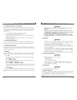
b) Armrest can now be easily removed for 

transferring.

4. Height Adjustment (option)

a) Release the upper securing lever (C).
b) Set at desired height.
c) Return securing lever to locked position.
d) Move armrest up or down to allow armrest to

snap into place.

K. HEIGHT-ADJUSTABLE ARMRESTS (OPTIONAL)

1. Installation

a) Slide the outer armpost into the receiver

mounted to the wheelchair frame.

b) The armrest will automatically lock into place.

2. Height Adjustment

a) Rotate release lever to stop.
b) Slide armrest pad up or down to desired height.
c) Return lever to locked position.
d) Push arm pad until upper armpost locks firmly

into place.

3. Removing Armrest

a) Rotate release lever and remove the armrest.

4. Replacing Armrest

a) Slide armrest back into receiver.
b) Return release lever to locked 

position against armpost.

5. Adjusting Armrest Receiver Fit

To tighten or loosen the fit of the outer armpost in the
receiver:

a) Loosen the four bolts on the sides of the

receiver.

b) With the armrest in the receiver, squeeze the

receiver to achieve the desired fit.

c) Tighten the four bolts.

6. Adjusting Inner Armpost Fit

a) Two set screws are installed in the outer arm-

post.

b) Turn the set screws in or out until the desired

fit is achieved.

I X .   S e t - u p ,   A d j u s t m e n t   &   U s e

930570 Rev. C

30

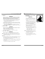
H. TO ADJUST THE HEIGHT OF THE REMOTE JOYSTICK

a) Remove the two pan-head screws (A), securing

the angle bracket mount (B).

b) Remove the Joystick from the mount by unfas-

tening the two screws (C) on the underside of
the mount.

c) Position angle bracket mount such that you

achieve the desired joystick height. Four posi-
tions are available by relocating the mount
either on the top or bottom of the mounting
bar (D) and/or by rotation of the angle
bracket mount.

I. REMOTE JOYSTICK SWING-AWAY RETRACTABLE

MOUNT (OPTIONAL)

The remote joystick is mounted with a mechanism
which allows the control to be locked in a forward or
retracted position using magnets.

1. Adjustment

a) To retract joystick, push outward on side of joy-

stick.

b) Push joystick away from front of armrest until it

locks into retracted position.

c) To return to forward position push joystick 

forward until it locks into place.

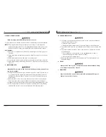
J. DUAL-POST HEIGHT-ADJUSTABLE 

FLIP-BACK ARMRESTS 

The dual-post flip-back armrest can be used as either a
flip-back armrest or a removable armrest.

1. Installing Armrest

a) Insert front and rear posts into armrest receivers.
b) Engage levers (A) and (B) to secure 

armrest.

2. Set-up for Flip-back Operation

a) Disengage lever (A) so front post is able to

come free.

b) Armrest now has the ability to be flipped back

without removal.

3. Removal of Armrest

a) Disengage both levers (A and B) so front and rear

post are able to come free.

A

B

A

C

B

D

C

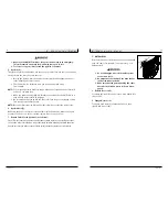
Height-Adjustable Armrest Key

1. Inner Arm Post

2. Receiver

3. Release Lever, Locked Position

4. Armrest Pad

5. Transfer Bar

6. Side Panel

7. Tension Adjustment Set Screw

8. Outer Arm Post

9. Receiver Adjustment Bolts

10. Receiver Release Lever

1

2

3

4

5

6

7

8

9

10

Summary of Contents for Quickie S-626

Page 1: ...uickie S 626 User Instruction Manual Warranty SUPPLIER THIS MANUAL MUST BE GIVEN TO THE RIDER OF THIS WHEELCHAIR RIDER BEFORE USING THIS WHEELCHAIR READ THIS ENTIRE MANUAL AND SAVE FOR FUTURE REFERENC...

Page 2: ...afety new prod ucts and options to increase your use and enjoyment of this wheelchair If you lose your warranty card call or write and we will gladly send you a new one FOR ANSWERS TO YOUR QUESTIONS Y...

Page 3: ...ng Parts 47 I Maintenance Chart 47 XIII WIRING DIAGRAMS 48 xIV SUNRISE LIMITED WARRANTY 49 I I T a b l e o f C o n t e n t s 930570 Rev C 4 I INTRODUCTION 3 II TABLE OF CONTENTS 4 III YOUR CHAIR AND I...

Page 4: ...ith angle adjustable footplates and heel loops Option elevating legrests and multipositional Casters Standard 8 airless insert Option 8 solid 8 pneumatic 9 solid insert 9 pneumatic Armrests Standard d...

Page 5: ...Other personal communication devices NOTE These devices can transmit signals while they are on even if not in use I V N o t i c e R e a d B e f o r e U s e 930570 Rev C 8 A CHOOSE THE RIGHT CHAIR SAF...

Page 6: ...s NOTE The following are not likely to cause EMI problems Lap top computers without phone or fax Cordless phones TV sets or AM FM radios CD or tape players D DISTANCE FROM THE SOURCE EM energy rapidly...

Page 7: ...V I G e n e r a l W a r n i n g s 930570 Rev C 12 Heed all warnings in this section If you fail to do so a fall tip over or loss of control may occur and cause severe injury to your or others A NOTIC...

Page 8: ...I G e n e r a l W a r n i n g s 930570 Rev C 14 G CHANGES ADJUSTMENTS Never use non Quickie parts or make a changes to your chair unless authorized by Sunrise Doing so will void the Warranty and may...

Page 9: ...Firmly grasp a rear wheel or an armrest with one hand This will help to prevent a fall if the chair tips P DRESSING OR CHANGING CLOTHES Be aware that your weight will shift if you dress or change clo...

Page 10: ...are very dangerous Even a small change in height may stop a caster wheel and cause your chair to tip You may need to Remove or cover threshold strips between rooms Install a ramp at entry or exit doo...

Page 11: ...roper design will vary depending on such things as the length and height of the ramp the need for an intermediate platform landing size doors and the direction of swing and whether the ramp includes a...

Page 12: ...Use a hand pump or a low volume air pump to inflate tires Use a tire gauge to check pressure 5 Driving over sharp objects may cause damage to pneumatic tires and tubes V I I W a r n i n g s C o m p o...

Page 13: ...device can help keep you from sliding down in the seat Consult your health care professional to find out if you need such a device 3 The belt must be snug but must not be so tight that it interferes w...

Page 14: ...torque wrench NOTE The wrench must measure inch pounds You can buy a torque wrench and prop er sockets from a hardware store V I I I T i p s f o r A t t e n d a n t s 930570 Rev C 26 1 Persons who he...

Page 15: ...th each other b Push together firmly 2 To disconnect Pull back on the retaining ring A of the lead cylindrical connector until it disconnects from the power cable C CHECK OUT Be sure this chair perfor...

Page 16: ...head screws A securing the angle bracket mount B b Remove the Joystick from the mount by unfas tening the two screws C on the underside of the mount c Position angle bracket mount such that you achiev...

Page 17: ...es installed Too much spring pre load may cause the spring to fail I X S e t u p A d j u s t m e n t U s e 930570 Rev C 32 L BACKREST A backrest angle adjustment is standard on the Trax Seat Frame 1 A...

Page 18: ...ension Rebound or damping is the rate at which the spring returns to its original position after experiencing a deflection a Adjustment of the rebound damping is done by turning the red knob C on the...

Page 19: ...by the four actuator lights H To exit drive or actuator mode select simply push the on off mode toggle up one or more times until the indicator no longer flashes or from the mode select push the joyst...

Page 20: ...n and move the joystick in the direction you want to go Moving the joystick from the neutral center position disengages the motor locks allowing the chair to move The chair will move faster the more y...

Page 21: ...rings watches pins and other metal jewelry that might contact battery terminal and cause a short A INTRODUCTION 1 Notes Batteries supply the power for your chair They contain a finite amount of ener...

Page 22: ...POSING OF BATTERIES 1 All batteries once they have reached the end of their useful life are deemed to be hazardous waste 2 For further information on handling and recy cling contact your local recycli...

Page 23: ...aintenance will improve performance and extend the useful life of your chair 2 Clean your chair regularly This will help you find loose or worn parts and will make your chair easier to use 3 To protec...

Page 24: ...r electrolyte level wet cell only Check plugs and connectors for proper connections Check all moving parts for wear Inspect all nuts bolts and fasteners for looseness or wear Inspect upholstery for we...

Page 25: ...f parts or changes not authorized by Sunrise Exceeding the weight limit b This warranty is void if the original chair serial number tag is removed or altered c This warranty applies in the USA only Ch...

Page 26: ......

Page 27: ...Sunrise Medical 7477 East Dry Creek Parkway Longmont Colorado 80503 USA 800 333 4000 In Canada 800 263 3390 2002 Sunrise Medical 7 02 930570 Rev C...

Reviews: