background image

108833 Rev. A

16

S - 6 3 6

I X .

L. BACKREST 

(FIG. 12)

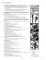
A backrest angle-adjustment is standard on the Trax Seat Frame.

1.  Adjustment on Trax Seat Frame

a) Remove the securing bolt (A) on the sides of the backrest hinge plate.
b) Set at desired angle. There are ten holes (in 4º increments) to choose from.
c) Reinstall the front bolt and tighten both bolts securely.

M. SEAT DEPTH 

(FIG. 13)

The seat depth can be adjusted continuously along the seat rail.

a) To adjust, loosen the four bolts (B) from each side of the backrest pivot plate.
b) Reposition the backrest to the desired position.
c) Retighten bolts on each side of the backrest pivot plate.

N.SEAT HEIGHT AND ANGLE ADJUSTMENT 

(FIG. 14, 15)

Adjusting the seat height can be done both at the front and the rear of the seat. Seat angle
can also be varied through front and rear seat height adjustments.

1. Front Seat Height Adjustment 

(FIG. 14)

a) Remove bolt (A) in the seat height strut (B). Adjust the upper and lower tube until the

desired front seat height is achieved. Each upper hole is 1" apart. Each lower hole is
1/2" apart. This allows 1/2" seat height increments.

b) Replace the bolt and secure the locknut.

2. Rear Seat Height Adjustment 

(FIG. 15)

a) Remove bolt (C).
b) Loosen bolt (D), but do not remove.
c) Adjust seat height to match one of three positioning holes (G). Each hole is 1" apart.
d) Refasten bolt (C) and retighten bolt (D).
e) To achieve 1/2" increments adjust position bolt (E) to either hole (F) and refasten.

O.WHEEL LOCKS 

(FIG. 16)

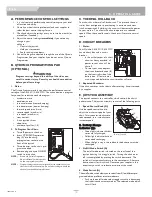
Wheel locks are installed by Sunrise when requested on the Quickie S-636.

1.  Mounting

The wheel lock mounts to the motor mount. Use a torque setting of 100 in./lbs when adjust-
ing wheel locks.

a) Loosen bolts (D).
b) Slide mounting bracket toward rear wheel until clamp embeds into tire to prevent

wheel movement when in locked position.

c) Tighten screws.

NOTE–

Wheel lock adjustment will be done through the drive-wheel spokes.

P. SUSPENSION 

(FIG. 17)

N

NO

O T

TE

E–

–   

Equivalent adjustments should be done to both the right and left suspension element.

It is important to properly adjust the pre-load and damping to ensure proper comfort and con-
trol for the rider.

1.  Pre-Load Adjustment

With the rider seated in the chair and with batteries installed, insure that the main horizontal
member of the base frame is parallel to the ground. If it is not parallel, adjust spring collar (B) in
either direction to adjust. If the rear of the base frame is lower than the front, adjust the spring
collar clockwise when viewed from the rear of the chair. If the rear of the base frame is higher
than the front, adjust the spring collar counter-clockwise when viewed from the rear of the chair. 

WARNING

The spring pre-load ring should never be adjusted so that the shock spring is
less than four inches long with the chair unoccupied and the batteries installed.
Too much spring pre-load may cause the spring to fail. 

A

B

move back
or forward

loosen all 4

A

B

E

F

D

C

G

12

13

14

15

D

C

B

16

17

Summary of Contents for QUICKIE S-636

Page 1: ...6 SC MPC Supplier This manual must be given to the user of this wheelchair User Before using this wheelchair read this entire manual and save for future reference S E C T I O N S E C T I O N E N G L I...

Page 2: ...ont Colorado 80503 303 218 4500 or 800 333 4000 FOR ANSWERS TO YOUR QUESTIONS Your authorized supplier knows your wheelchair best and can answer most of your questions about chair safety use and maint...

Page 3: ...ic Tires 11 J Positioning Belts Optional 12 K Push Handles 12 L Rear Wheel Locks Optional 12 M Seating Systems 12 N Upholstery Fabric 12 VIII TIPS FOR ATTENDANTS 12 A To Climb a Curb or Single Step 12...

Page 4: ...ndard Non folding 15 24 Footrest Standard Swing away with angle adjustable footplates and heel loops Option elevating legrests and multiposi tional Casters Standard 8 airless insert Option 8 solid 8 p...

Page 5: ...of function and ability level C REVIEW THIS MANUAL OFTEN Before using this chair you and each person who may assist you should read this entire Manual and make sure to follow all instructions Review t...

Page 6: ...e Switch Soft Switch Grasp Switch Wobble Switch WARNING Heed all warnings to reduce the risk of unintended brake release or chair movement 1 Beware of the danger from hand held transceivers Never turn...

Page 7: ...or tip over is likely 4 Remind the rider to lean back when you tilt the chair backward 5 Lower the chair slowly Do not let the chair drop to the pavement or ground Doing so may damage the chair or in...

Page 8: ...all or tip over G CHANGES ADJUSTMENTS WARNING Never use non Quickie parts or make a changes to your chair unless authorized by Sunrise Doing so will void the Warranty and may create a safety hazard 1...

Page 9: ...to reach 2 Rotate the front casters until they are as far forward as possi ble This makes the chair more stable NOTE To do this Move your chair past the object you want to reach then back up alongside...

Page 10: ...l or tip over T TO REDUCE THE RISK OF A FALL TIP OVER OR LOSS OF CONTROL WARNING 1 Never use your chair on a slope unless you are sure you can do so without losing traction 2 Always go as straight up...

Page 11: ...ts See Section IX Set Up Adjustment Use for prop er torque settings F FOOTRESTS WARNING 1 At the lowest point footrests should be at least 2 1 2 inch es off the ground If set too LOW they may hang up...

Page 12: ...ily remove the belt in an emergency 5 Never use a positioning belt In place of a motor vehicle seat belt In an accident or sudden stop you may be thrown from the chair A posi tioning belt will not pre...

Page 13: ...OTE Unless otherwise noted use a torque setting of 120 inch pounds for all fasteners B TOOLS YOU WILL NEED 1 Basic Tool Kit To set up adjust and maintain your chair you will need the following tools 7...

Page 14: ...s G into place on locking bolt 2 Removal a To remove footrest press quick release lever H b Rotate footrest outward and lift 3 Height Adjustment a Loosen both bolts A in the hanger frame tube b Reposi...

Page 15: ...rmrest a Disengage both levers A and B so front and rear post are able to come free b Armrest can now be easily removed for transferring 4 Height Adjustment option a Release the upper securing lever C...

Page 16: ...2 increments adjust position bolt E to either hole F and refasten O WHEEL LOCKS FIG 16 Wheel locks are installed by Sunrise when requested on the Quickie S 636 1 Mounting The wheel lock mounts to the...

Page 17: ...the rider out of the seat Turn the red knob a half turn clockwise and test for performance Q CHECK OUT Once the wheelchair is assembled and adjusted it should roll smoothly and easily All accessories...

Page 18: ...4 Mode Switch A The on off mode switch allows you to select from 5 five different pro grammable drive profiles or actuator mode sets Push up the on off mode select toggle switch to index among the fi...

Page 19: ...the chair will slow to a stop and the motor locks will reengage We recommend that you switch the chair off if you stop for any length of time This will conserve battery power NOTE Once the chair stop...

Page 20: ...B BATTERY CHARGER A battery charger produces a direct current DC When applied to a discharged battery this reverses the chemical reaction that led to its discharge 1 Charge Rate How fast a battery wil...

Page 21: ...teries 3 Always wear rubber gloves and safety glasses when you handle batteries 4 Before working around batteries remove all metal personal effects such as necklaces rings watches pins and other metal...

Page 22: ...injury or death from electri cal shock fire or explosion while charging 1 Never connect charger to a 240 volt source The mains input voltage is 110 volts 2 Never touch the charger after it is connecte...

Page 23: ...area If you fail to do so parts may rust or corrode 2 Before using your chair make sure it is in proper working order Inspect and service all items on the Maintenance Chart 3 If you store this chair...

Page 24: ...rim e Repair or replace inner tube f Reassemble the caster wheel makesure the bearing spacer is in place and all four bolts are secure NOTE Use a torque setting of 240 inch pounds when tightening bol...

Page 25: ...s chart at the indicated intervals If any of the items are loose worn bent or distorted immediately have them checked and or repaired by your authorized Sunrise supplier Frequent maintenance and servi...

Page 26: ...108833 Rev A 26 S 636 XIII WIRING DIAGRAM WIRING DIAGRAM DETAIL REMOTE JOYSTICK...

Page 27: ...or altered 3 This warranty applies in the USA only Check with your sup plier to find out if international warranties apply 4 This warranty is not transferable and only applies to the first consumer p...

Page 28: ...Sunrise Medical Inc 7477 East Dry Creek Parkway Longmont Colorado 80503 USA 800 333 4000 In Canada 800 263 3390 www sunrisemedical com 2009 Sunrise Medical Inc 7 09 108833 Rev A...

Reviews: