background image

930487 Rev. B

I X .   S e t - U p   &   A d j u s t m e n t

33

I X .   S e t - U p   &   A d j u s t m e n t

930487 Rev. B

32

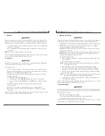
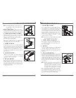
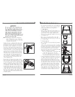
nut (B) down to the axle plug (C). Never allow a gap
greater than .800" (20mm) between the outside face
of the aluminum nut and the inside face of the axle
sleeve. Adjusting the axle sleeve out too far can dam-
age both the axle plug and the axle sleeve. Tighten
aluminum nut down to 200 in/lbs of torque. Repeat for
opposite side making sure the gap between the head of
the axle sleeve and the face of the aluminum nut are
the same on both sides (failure to do so will cause the
chair to track improperly). Place rear wheel axles back
into camber tube’s threaded sleeve.

J. CASTERS

NOTE– 

Setting the wheelchair on a flat surface table or
a workbench helps make these procedures easier.

NOTE ON TORQUE SETTING–

A torque setting is the

optimum tightening which should be made on a particu-
lar fastener. Use proper torque settings when specified.

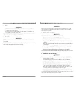
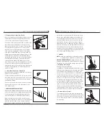
1. Adjusting Caster Angle

Checking for Caster Squareness:
Your Quickie Ti Titanium wheelchair leaves the factory
with the casters adjusted square. Any time you change
your wheelchair rear axle height (see Letter F), rear
tire size, center of gravity position or camber tube, you
should check that the casters are still square. A caster
that is not square will result in the caster lifting off
the floor as it rotates around the stem bolt (A). Check
for squareness by placing your wheelchair on a flat,
horizontal surface. Rotate both forks so that the cast-
ers are towards the rear of the wheelchair. Place a
square or pocket level (B) against the flat surface on
the rear of the fork and note whether this surface is
vertical (square). If this surface is more than 1 degree
away from vertical, your casters require re-squaring.

2. Re-squaring Your Casters

To re-square your casters, you must first remove the
right caster. (Note: Do not disassemble the left caster
at this time.) Loosen and remove the axle using two T-
25 Torx wrenches. Be certain to set aside the spacers
for reassembly.

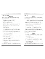
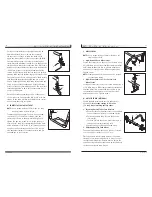
4. Compensating for Seat Sling Tension

Before loosening any of the hardware that secures the
camber tube (See Rear Seat Height Adjustment and
Toe-in or Toe-out) follow the instructions below.

The tension in the seat sling will tend to pull the axle
plates inward when the hardware securing the axle
plates to the camber tube is loosened. To insure that
the axle plates are returned to the correct position,
mark the location of the axle plates on the camber
tube by placing a small strip of tape on the camber
tube next to the OUTSIDE edge of the axle plate. (A)
Always return the axle plates to these positions on the
camber tube when the chair is reassembled. During
reassembly, begin with one side of the chair and align
the axle plate with the tape. Tighten the hardware
securing the axle plate to the camber tune on this
side. Check for proper toe in/out adjustment according
to Section H-3. Next spread the axle plates apart so
that the axle plate on the opposite side is aligned with
the tape, and tighten the associated hardware to 65
in-lbs. (7.3 Nm). 

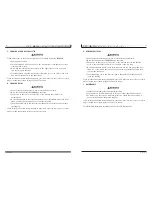
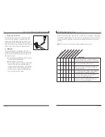
5. Rear Wheel Axle Sleeve Adjustment

Tight axle sleeves should be maintained for proper per-
formance of the wheelchair.

To adjust the axle you will need a 3/4" wrench to turn
the outside axle nuts. You will also need a 1/2" wrench
to secure the axle on the ball-lock end, and prevent
the axle from turning.

Turn the outside axle nut counter clockwise to tighten.
There should only be zero to ten thousandths of an
inch (.010) of play.

I. WHEELBASE WIDTH ADJUSTMENT

Adjusting the wheelbase width allows the rider the option
to move the wheels closer or further away from the chair.
It also compensates for camber adjustment and gives
proper wheel spacing to maximize pushing efficiency.

Adjust threaded axle sleeve (A) to desired location,
making sure that the rear wheel does not interfere with
either the backrest tube or any mounting hardware.
Once desired location is achieved, run the aluminum

A

B

1° MAX

A

C

B

A

Summary of Contents for Quickie Ti Titanium

Page 1: ...kie Ti Titanium User Instruction Manual Warranty SUPPLIER THIS MANUAL MUST BE GIVEN TO THE RIDER OF THIS WHEELCHAIR RIDER BEFORE USING THIS WHEELCHAIR READ THIS ENTIRE MANUAL AND SAVE FOR FUTURE REFER...

Page 2: ...fety new products and options to increase your use and enjoyment of this wheelchair FOR ANSWERS TO YOUR QUESTIONS Your authorized supplier knows your wheelchair best and can answer most of your questi...

Page 3: ...39 D Cleaning 39 E Storage Tips 39 XII SUNRISE LIMITED WARRANTY 40 I I T a b l e o f C o n t e n t s 930487 Rev B 4 I INTRODUCTION 3 A Sunrise Listens 3 II TABLE OF CONTENTS 4 III YOUR CHAIR AND ITS...

Page 4: ...td stainless steel Opt titanium quad release axle nuts Anti tip Tubes Opt Rear anti tip tubes Standard Rear Wheels Std spoke Quickie Performance Wheels Opt heat treated Opt Spinergy Tire Size Std 24 O...

Page 5: ...severe injury to the rider or others I V N o t i c e R e a d B e f o r e U s e 930487 Rev B 8 A CHOOSE THE RIGHT CHAIR SAFETY OPTIONS Sunrise provides a choice of many wheelchair styles to meet the ne...

Page 6: ...Of Your Chair 1 Make sure the chair rolls easily and that all parts work smoothly Check for noise vibration or a change in ease of use They may indicate low tire pressure loose fasteners or damage to...

Page 7: ...makes the chair more stable 2 Lock anti tip tubes in place If your chair does not have anti tip tubes back it up against a wall and lock both rear wheels If you fail to heed these warnings damage to y...

Page 8: ...rear wheels hits an object and stops rolling 1 Propel your chair slowly and smoothly 2 If your chair has anti tip tubes make sure to lock them in place 3 Stop often and check to be sure your path is...

Page 9: ...loosen fasteners If you fail to heed these warnings damage to your chair a fall tip over or loss of control may occur and cause severe injury to the rider or others V I W a r n i n g s F a l l s T i p...

Page 10: ...he curb or step turn the chair around and pull it backward 3 While looking over your shoulder carefully step back until you are off the curb or stair and standing on the lower level 4 Pull the chair t...

Page 11: ...der or others For additional maintenance information see Section XII Maintenance V I I W a r n i n g s F o r S a f e U s e 930487 Rev B 20 C CLIMBING A CURB OR SINGLE STEP Follow these steps to help t...

Page 12: ...nflated tires may burst If you fail to heed these warnings damage to your chair a fall tip over or loss of control may occur and cause severe injury to the rider or others V I I I W a r n i n g s C o...

Page 13: ...may occur and cause severe injury to the rider or others V I I I W a r n i n g s C o m p o n e n t s O p t i o n s 930487 Rev B 24 G POSITIONING BELTS OPTIONAL Use positioning belts ONLY to help suppo...

Page 14: ...system not approved by Sunrise may alter the center of balance of this chair This may cause the chair to tip over 1 Do not change the seat system of your chair UNLESS you consult your authorized supp...

Page 15: ...uareness of the casters Letter I If you change your center of gravity position re adjust these if necessary Before adjusting your wheelchair s center of gravity locate the additional saddles supplied...

Page 16: ...X S e t U p A d j u s t m e n t 930487 Rev B 30 The more you move your rear wheels forward the more likely your chair will tip over back wards Always make adjustment in small incre ments and check the...

Page 17: ...r at this time Loosen and remove the axle using two T 25 Torx wrenches Be certain to set aside the spacers for reassembly 4 Compensating for Seat Sling Tension Before loosening any of the hardware tha...

Page 18: ...t the second anti tip tube wheel the same way Both wheels should be exactly the same height Loosen the stem bolt A on the right fork using an 8mm Allen wrench Do not remove the stem bolt Simply loosen...

Page 19: ...should also perform smoothly If you have any problems fol low these procedures a Review assembly and adjustment sections to make sure chair was properly prepared b Review trouble shooting guide c If y...

Page 20: ...n proper working order Inspect and service all items on the Maintenance Chart Letter B 3 If stored for more than three months have your chair inspected by an authorized supplier before use A INTRODUCT...

Page 21: ...is removed or altered 3 This warranty applies in the USA only Check with your supplier to find out if international warranties apply D WHAT WE WILL DO Our sole liability is to repair or replace cover...

Page 22: ...10 03 930487 Rev B Sunrise Medical 7477 East Dry Creek Parkway Longmont Colorado 80503 USA 303 218 4600 800 333 4000 In Canada 800 263 3390 This product is manufactured to comply with the Medical Devi...

Reviews: