background image

930482 Rev. A

X .   O p e r a t i n g   G u i d e

35

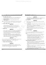
• When you release the joystick it will return to

neutral; the chair will slow to a stop and the
motor locks will reengage.

• We recommend that you switch the chair off if

you stop for any length of time. This will con-
serve battery power.

NOTE–

Once the chair stops, switching the chair off

will not affect the motor locks. 

6. Joystick Boot (H)

Make sure the boot is not torn or cracked (this could
allow debris, water or moisture to enter). If the boot is
torn or cracked, replace it as soon as you can.

1. Never use the ON/OFF switch to stop your chair

except in an emergency. This will result in an
abrupt stop and may cause you to fall.

2. To slow or stop your chair, return the joystick to

neutral.

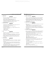
F. MOTOR LOCKS 

Disconnect the motor locks when you need to manually
push the chair. (For example, in an emergency, or if
batteries fail).

1. Do not disengage motor locks unless power to

the chair is off.

2. Be aware that the chair will not have brakes

in the free-wheel position.

3. Make sure that the person pushing the chair has

full control when motor locks are disengaged.

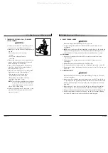
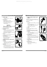
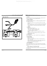
1. Disengaging Drive 

a. Facing the back of the chair, pull lever A 

(left side) into the inward position (as 
shown in diagram).

b. Push lever B (right side) into the inward 

position (as shown in diagram).

2. Engaging Drive

a. Reverse the procedure described above.

NOTE– 

Always engage the drive when parking, 
particularly if the chair is occupied.

X .   O p e r a t i n g   G u i d e

930482 Rev. A

34

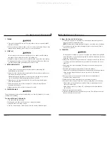
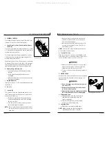
E. INTEGRAL JOYSTICK

The standard integral joystick controls the chair’s per-
formance. It consists of the following parts:

1. Speed Control or Drive Mode Selection Buttons

(A and B)

To decrease the speed level depress button A. Or, when
1- 5 Drive modes are programmed, depress button A to
activate lower drive mode(s).

To increase speed level, depress button B. Or, when 1-
5 Drive modes are programmed, depress button B to
activate higher drive mode(s).

Speed level active, or Drive Mode selected, is indicated
on display (C) by a series of five lights. One light indi-
cates slowest level/mode currently active, while five
lights indicates highest level/mode currently active.

2. Battery Charge Indicator (D)

• Green lights indicate that batteries are fully

charged. 

• Yellow lights indicate that batteries need

recharging. 

• When the lights stay in the red band, the batter-

ies must be recharged.

3. On/Off Button (E)

Turning the chair on or off is accomplished by depress-
ing button E.

4. Horn (F)

5. Joystick (G)

The joystick controls the direction and speed of your
chair. Turn the chair on and move the joystick in the
direction you want to go.

• Moving the joystick from the neutral (center)

position disengages the motor locks, allowing
the chair to move. 

• The chair will move faster the more you move

the joystick away from neutral. 

NOTE–

If your speed becomes hard to manage, release
the Joystick and the chair will come to a com-
plete stop.

A

B

To disengage the motor locks

A

D

E

F

G

H

B

C

Integral Joystick

All manuals and user guides at all-guides.com

Summary of Contents for Quickie V-100

Page 1: ...l Warranty SUPPLIER THIS MANUAL MUST BE GIVEN TO THE RIDER OF THIS WHEELCHAIR RIDER BEFORE USING THIS WHEELCHAIR READ THIS ENTIRE MANUAL AND SAVE FOR FUTURE REFERENCE All manuals and user guides at al...

Page 2: ...ptions to increase your use and enjoyment of this wheelchair If you lose your war ranty card call or write and we will gladly send you a new one FOR ANSWERS TO YOUR QUESTIONS Your authorized supplier...

Page 3: ...IAGRAM 46 XIV SUNRISE LIMITED WARRANTY 47 I I T a b l e o f C o n t e n t s 930482 Rev A 4 I INTRODUCTION 3 II TABLE OF CONTENTS 4 III YOUR CHAIR AND ITS PARTS 6 IV NOTICE READ BEFORE USE 8 V EMI ELEC...

Page 4: ...grests angle adjustable extended and platform flip up footplates toe loops exten sion tubes Casters Standard 8 pneumatic Option 8 airless insert Armrests Standard height adjustable with standard or fu...

Page 5: ...ation devices NOTE These devices can transmit signals while they are on even if not in use I V N o t i c e R e a d B e f o r e U s e 930482 Rev A 8 A CHOOSE THE RIGHT CHAIR SAFETY OPTIONS Sunrise prov...

Page 6: ...rn or climb or descend at an angle a fall or tip over is likely 4 Remind the rider to lean back when you tilt the chair backward 5 Lower the chair slowly Do not let the chair drop to the pavement or g...

Page 7: ...chair on a slope or ramp if there is snow ice water or oil film present When in doubt have someone help you 3 When not in use keep your chair in a clean dry place V I G e n e r a l W a r n i n g s 93...

Page 8: ...This will reduce the risk that you will miss the seat or fall V I G e n e r a l W a r n i n g s 930482 Rev A 14 J TERRAIN 1 This chair is designed for use on firm even surfaces such as concrete asphal...

Page 9: ...use a fall or tip over 4 A drop off at the bottom of a slope A drop off of as small as 3 4 inch can stop a front caster and cause the chair to tip forward V I G e n e r a l W a r n i n g s 930482 Rev...

Page 10: ...tom of the platform These may cause a fall or tip over When in doubt have someone help you 3 Always position the rider securely in the chair to help prevent falls while on a lift 4 Avoid moving forwar...

Page 11: ...the relief of pressure 2 If you suffer from pressure sores or if you are at risk that they will occur you may need a special seat system or a device to control your posture Consult your doctor nurse...

Page 12: ...tose or agitated K PUSH HANDLES 1 Push handles provide secure points for an attendant to propel and control the chair This helps to prevent a fall or tip over 2 Check to make sure push handle grips wi...

Page 13: ...s balance point This will lift the front casters off the curb or step 6 Keep the chair in balance and take small steps backward Be sure to look where you are going Turn the chair around and gently low...

Page 14: ...ill operate smoothly Check to see that all components work properly If you detect a problem be sure to correct it before use I X S e t U p A d j u s t m e n t U s e 930482 Rev A 26 NOTES 1 Work Surfac...

Page 15: ...s e 930482 Rev A 28 A BATTERY REMOVAL To remove the batteries for transporting or servicing 1 Remove Batteries a Unplug batteries from controller b Unfasten the battery hold down straps A c Remove ba...

Page 16: ...tails on how to contact your authorized sup plier or Sunrise customer service I X S e t U p A d j u s t m e n t U s e 930482 Rev A 30 5 Adjusting Armrest Receiver Fit To tighten or loosen the fit of t...

Page 17: ...it is required before the circuit break er s will reset 2 Repeated Shutdown If the chair continues to shut down after resetting have it serviced by a supplier X O p e r a t i n g G u i d e 930482 Rev...

Page 18: ...cularly if the chair is occupied X O p e r a t i n g G u i d e 930482 Rev A 34 E INTEGRAL JOYSTICK The standard integral joystick controls the chair s per formance It consists of the following parts 1...

Page 19: ...at least 15 minutes Seek medical attention immediately X I B a t t e r i e s 930482 Rev A 36 A INTRODUCTION 1 Notes Batteries supply the power for your chair They contain a finite amount of energy and...

Page 20: ...scharged state Unused or stored batteries should be given a charge once per month 7 Charge batteries by engaging the battery charger connector A to the charger programmer port B located on the joystic...

Page 21: ...rs Clean around motor area weekly with a slightly damp not wet cloth Wipe off or blow away any fluff dust or dirt on or around the motors NOTE You do not need to grease or oil the chair 3 Upholstery H...

Page 22: ...bearing spacer is in place and all four bolts are secure NOTE Use a torque setting of 240 inch pounds when tightening bolts X I I M a i n t e n a n c e 930482 Rev A 42 D BATTERY MAINTENANCE 1 To preve...

Page 23: ...a torque setting of 420 in lbs to re tighten nut Bend washer tabs up to secure nut and install plastic dome plug g Inflate tire to proper pressure level listed on tire sidewall G MOTOR BRUSHES Check t...

Page 24: ...r altered c This warranty applies in the USA only Check with your supplier to find out if international warranties apply 4 WHAT WE WILL DO Our sole liability is to repair or replace covered parts This...

Page 25: ...Sunrise Medical 7477 East Dry Creek Parkway Longmont Colorado 80503 USA 800 333 4000 In Canada 800 263 3390 2002 Sunrise Medical 12 02 930482 Rev A All manuals and user guides at all guides com...

Reviews: