background image

38

ENGLISH

Argon

2

 Rev.C

Wheel alignment

Adjusting The Wheel Alignment


Important:

 To achieve the very best movement, the rear 

wheels must be adjusted to their optimum position, which 

means correctly adjusting the wheel alignment. 

To do this, measure the distance between both wheels 

front and rear to ensure that they are parallel to one 

another. 

The difference between both measurements should not 

exceed 5 mm. 

To adjust the wheels to make them parallel, loosen the 

screws and turn the axle sleeve accordingly. Make sure 

that after any adjustment work, all screws are tightened 

correctly (see the page on torque).

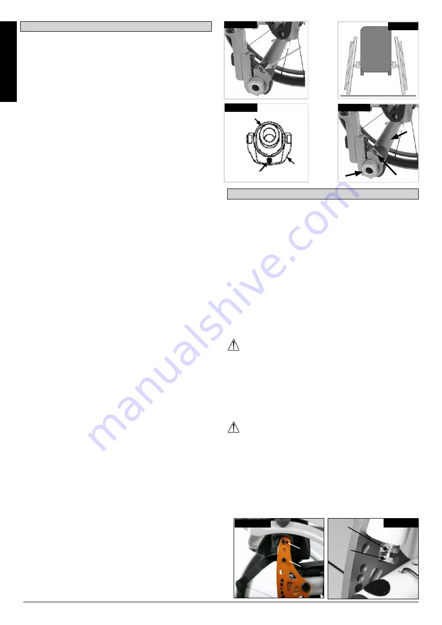
Argon2 Tracking Adjustment

Setting the toe-in/toe-out to zero.

NOTE:

 A wheelchair with 0° camber cylinders cannot 

have toe-in or toe-out. This setting is necessary only with 

3°, 6

°

 and 9° camber cylinders.

The term "toe-in or toe-out" defines how well the rear 

wheels of the chair are aligned in relation to the ground. 

This determines how well the chair will run. Normal 

resistance or rolling resistance is present when toe-in is 

set to zero.
To set toe-in/toe-out to zero: loosen the Allen screws (1) 

(1 on each side), which secure the angle tube clamp. 

Check the ball in the horizontal (2) plane and turn the 

angle tube (3) until the ball is in the centre. Toe-in is now 

zero.

Before tightening the screws (1), check that the camber 

tube is centred left-to-right. The gap should be the same 

on both sides, or there should be no gap at all. Tighten the 

screws to 7 Nm. (Fig. 4.21-4.23).

Adjusting the Rear Wheelbase Width:

The rear wheelbase is defined as the distance between 

the upper side of the rear wheels and the backrest tubes, 

and is represented by factory setting (1.25 cm). This has 

to be increased if a larger gap between the tyres and the 

optional height-adjustable armrests has to be created 

(Fig. 4.24).

NOTE:

 When adjusting the rear wheelbase, adjust first 

one wheel then the other. If both sides are loosened at the 

same time, this will alter the toe-in/toe-out adjustment. To 

adjust the rear wheelbase, the parts of the camber (4) 

move telescopically into or out of the camber tube (5), and 

lock into place when they reach the end. Loosen screw (6) 

(located closest to the camber tube) on the left side of the 

chair. Move the quick-release axle inwards or outwards to 

achieve the desired wheelbase. Tighten the screws to 7 

Nm. Repeat this procedure on the right side of the chair 

and adjust the gap so that it is the same amount as on the 

left side.

Fig. 4.23

BALL

3

2

Angle-Adjustable Back

The backrest angle is adjusted by altering the position of 

the pin in the backrest mounting. The pin (1) must be 

completely clicked into place in the hole pattern on both 

sides, this gives you an angle adjustment of 8.5°.

Fit the red plastic pins into the unused holes. To reach a 

smaller angle increment (3.5°), you open the allen key 

screw (2) and re-set the screw into the second hole. 

Please use the relevant torque force (see matrix) to 

tighten the screw (2). 

This gives you 12° change in the back angle. Then move 

the pin (1) in the opposite direction to the next hole, which 

gives you 12° - 8°= 3.5° change. (Fig. 4.25)
To reduce the play in the backrest, the nut (1) can be 

released, then the optimal position can be set using the 

set screw (2). Then re-tighten the nut (1). (Fig. 4.26).

CAUTION ! 

The screws must be re-tightened. Otherwise the angle 

adjustment will be lost.

Folding Backrest

Release the backrest by pulling the cord. At the same 

time, push it forward to fold it down. To return the backrest 

to its original position, this must be pulled back as far as 

possible, until it locks into place on both sides.

CAUTION ! 

When folding the backrest down, please make sure that 

your fingers do not get caught.

Backrest

Fig. 4.25

1

2

Fig. 4.26

1

2

1

Fig.4.21

4

5

6

Fig.4.24

Fig. 4.22

Summary of Contents for Sopur Argon2

Page 1: ...Argon2 GEBRAUCHSANWEISUNG DIRECTIONS FOR USE NOTICE D UTILISATION MANUALE D USO ROLLSTUHL WHEELCHAIR FAUTEUIL ROULANT CARROZZINA 000690386 02 ...

Page 2: ...ptions ou accessoires illustrés sont disponibles moyennant un coût supplémentaire FR Wheelchair Components We at SUNRISE MEDICAL have been awarded the ISO 13485 certificate which affirms the quality of our products at every stage from R D to production This products meet the requirements in accordance with EC guidelines Options or accessories shown are available at extra cost EN Rollstuhlkomponent...

Page 3: ...éverrouillage rapide 10 Freins 11 Main courante 12 Roue arrière Table of Contents 29 Sommaire 50 1 2 3 4 5 6 7 8 9 10 11 12 Rollstühle 1 Schiebegriffe 2 Rückenbespannung 3 Seitenteil 4 Sitzbespannung 5 Fußraste 6 Lenkräder 7 Fußbrett 8 Gabel 9 Steckachse 10 Feststellbremsen 11 Greifring 12 Antriebsrad Inhaltsverzeichnis 8 Carrozzina 1 Maniglie di spinta 2 Telo schienale 3 Spondina 4 Telo seduta 5 ...

Page 4: ...0 760 560 1120 690 MAX mm MIN mm 520 440 500 300 365 230 567 540 10 0 10 0 15 0 15 31 100 92 500 220 450 250 500 300 10 0 6 9 MAX kg MIN kg 140 15 0 9 0 10 0 710 510 MAX MIN MAX MIN 325 275 11 100 2 1 KG X X X Kg MAX MAX mm MIN mm ...

Page 5: ...5 Argon2 Rev C 44 45 46 47 48 49 50 3 75 mm 1 1 2 2 3 4 98 mm 1 1 2 2 3 3 5 124 mm 1 1 2 3 3 2 1 111 mm h 1 0 cm ...

Page 6: ...6 Argon2 Rev C 45 46 47 48 49 50 51 52 3 75mm 1 1 2 2 3 4 98mm 1 1 2 3 3 5 124mm 1 1 2 3 6 140mm 1 1 2 3 3 2 1 h 123 mm ...

Page 7: ...9 A2 48 A3 A4 47 A4 45 A5 A6 44 A6 A7 43 24 540 6 9 A7 0 3 42 A8 41 A9 40 B2 39 B3 37 B4 36 B5 50 A2 49 A3 48 A4 47 A5 45 A6 A7 44 6 9 A7 0 3 43 25 559 A8 42 A9 A8 41 B2 39 B3 38 B4 37 B5 52 A2 A4 50 A3 49 A4 A5 48 A5 47 A6 46 26 590 6 9 A7 45 A8 0 3 43 A9 42 B2 41 B3 40 B4 39 B5 100mm 100mm h h h h h ...

Page 8: ...eise nicht in allen Einzelheiten genau Ihrem eigenen Modell Dennoch sind alle Anweisungen trotz möglicher Detailunterschiede völlig relevant Der Hersteller behält sich das Recht vor Gewichte Abmessungen oder andere in diesem Handbuch aufgeführte technische Daten ohne vorherige Benachrichtigung zu ändern Alle in diesem Handbuch aufgeführten Zahlenangaben Abmessungen und Kapazitäten sind ungefähr un...

Page 9: ...brauch sicher auf zubewahren und nicht zu entsorgen Kombinationen von Medizinprodukten Dieses Medizinprodukt kann unter Umständen mit einem oder mehreren anderen Medizinprodukten bzw anderen Produkten kombiniert werden Informationen darüber welche Kombinationen möglich sind finden Sie unter www Sunrisemedical de Alle aufgeführten Kombina tionen wurden überprüft um die grundlegenden Sicher heits un...

Page 10: ...öglichst nach außen weggeschwenkt werden Begeben Sie sich immer so nah wie möglich an die Stelle an der Sie sitzen möchten Setzen Sie Ihren Rollstuhl nur bestimmungsgemäß ein Vermeiden Sie z B ein ungebremstes Fahren gegen ein Hindernis Stufen Bordsteinkante oder Herunterfahren von Kanten Die Feststellbremsen sind nicht dazu vorgesehen den Rollstuhl während der Fahrt abzubremsen Sie sichern den Ro...

Page 11: ...e Rückenlehne Ihres Rollstuhls kann die Stabilität Ihres Rollstuhls nach hinten beeinträchtigen vor allem wenn der Rückenwinkel nach hinten verstellt wurde Der Rollstuhl kann dadurch nach hinten kippen und Verletzungen verursachen Bei Oberschenkelamputation müssen die Sicherheitsräder verwendet werden Achten Sie vor Fahrtantritt auf den korrekten Luftdruck der von Ihnen verwendeten Bereifung Bei d...

Page 12: ...ber einen Ankippbügel verfügt und das Rückenrohr ständig als Hebel zum Kippen des Rollstuhls benutzt wird kann dadurch das Rückenrohr beschädigt werden Fig 2 2 1 Transportieren des Rollstuhls Um den Stuhl so kompakt wie möglich zu halten können Sie die Hinterräder abnehmen Die Rückenlehne kann nach unten geklappt werden dazu die Schnur 1 siehe Abbildung 3 an der Rückenlehne ziehen Fig 3 0 3 1 Ohne...

Page 13: ...Die Schraube dann wieder anziehen Fig 4 1 und 4 2 VORSICHT Prüfen Sie den Abstand der Feststellbremsen nach jeder Justierung des Hinterrads und stellen Sie ihn gegebenenfalls neu ein Bremshebelverlängerung Mit einem längeren Hebel brauchen Sie weniger Kraft um die Feststellbremsen zu betätigen Die Bremshebelverlängerung ist mit der Bremse verschraubt Durch Hochziehen kann diese nach vorne geklappt...

Page 14: ...ellbremse an einer Stelle anbringen an der sie ordnungsgemäß funktioniert Fig 4 6 VORSICHT Die unsachgemäßige Montage der Einhand Feststellbremse kann zu schweren Verletzungen des Fahrers und anderer Personen führen Fig 4 5 Fig 4 6 Handbike Achse Die Handbike Achse muss so eingestellt dass sich der Schwerpunkt nach hinten verlagert Das ermöglicht die sichere Benutzung des Handbike Zubehörs Fig 4 7...

Page 15: ...ch Diese können hochgeklappt werden um das Ein und Aussteigen zu erleichtern Fig 4 11 Fußraste Kunststoff Fußplatten Die Fußplatten können hochgeklappt werden um das Ein und Aussteigen zu erleichtern Fig 4 15 Fig 4 11 1 Fig 4 12 1 Fig 4 13 2 2 5 cm 15 DEUTSCH Argon2 Rev C Einstellen der Fußraste WARNUNG Begleitperson Nicht auf dem Fußbrett stehen Auch wenn der Fahrer im Rollstuhl sitzt besteht Kip...

Page 16: ...ellung des Sturzes stimmt nicht Der Luftdruck im Lenkrad und oder Hinterrad ist nicht korrekt die Räder drehen sich nicht ausreichend Die optimale Einstellung der Lenkräder bildet die Voraussetzung für den Geradeauslauf des Rollstuhls Die Laufräder müssen immer von einem zugelassenen Fachhändler eingestellt werden Jedes Mal wenn die Hinterradposition geändert wurde müssen die Radaufnahme neu einge...

Page 17: ... werden muss Fig 4 24 HINWEIS Beim Einstellen des Radstandes hinten zuerst ein Rad und dann das andere einstellen Wenn beide Seiten gleichzeitig gelöst werden wird die Einstellung der Vorspur Nachspur geändert Beim Einstellen des Radabstandes hinten bewegen sich die Steckteile des Sturzes 4 teleskopartig in das Sturzrohr hinein bzw aus dem Sturzrohr 5 heraus und rasten jeweils am Ende des Weges ei...

Page 18: ...ntiert ist b Die Armlehne rastet automatisch ein 2 Höheneinstellung a Drehen Sie den Verschlusshebel für die Höhenverstellung 2 zum zweiten Stopp b Schieben Sie das Armpolster auf oder abwärts auf die gewünschte Höhe c Stellen Sie den Hebel wieder in die verriegelte Stellung gegen die Armlehnenschiene d Drücken Sie auf das Armpolster 4 bis die Schiene sicher einrastet 3 Die Armlehne entfernen a Be...

Page 19: ...ff kann leicht in die gewünschte Position gebracht werden Mit der Mutter am Spannhebel wird eingestellt wie fest die Schiebegriffe geklemmt werden Wenn die Mutter nach dem Einstellen des Spannhebels lose ist sitzt der Schiebegriff auch zu locker Vor dem Gebrauch den Schiebegriff drehen um sicherzustellen dass er fest genug geklemmt ist Nach der Höheneinstellung der Griffe den Spannhebel 1 wieder g...

Page 20: ...n 7 Nm verwenden 1 Einschieben der Sicherheitsräder in die Klemme a Drücken Sie den hinteren Knopf am Adapter für das Sicherheitsrad so dass beide Auslösestifte nach innen gezogen werden b Schieben Sie die Sicherheitsräder 1 in den Adapter für das Sicherheitsrad c Drehen Sie die Sicherheitsräder nach unten bis der Auslösestift in der Klemme einrastet d Das zweite Sicherheitsrad genauso einbauen Ak...

Page 21: ... Bedürfnisse des Benutzers an Gurt kürzen Gurt verlängern Übrige Gurtlän ge durch den Einsteckteil des Steckverschlusses und die Schlaufe zurück fädeln Darauf achten dass der Gurt am Einsteckteil des Steckverschlusses keine Schlinge aufweist Um den Gurt zu verlängern übrige Gurtlänge durch die Schlaufen und den Einsteckteil des Steckverschlusses fädeln Nach dem Anschnallen den Abstand zwischen dem...

Page 22: ...d die Passform des Gurts regelmäßig zu überprüfen um die Gefahr zu verringern dass der Endbenutzer den Gurt aus Versehen zu lang einstellt Fig 4 44 5 0 Reifen und Montage Vollgummireifen gehören zur Standardausstattung Stellen Sie bei Luftreifen immer sicher dass sie den richtigen Luftdruck aufweisen da sonst die Leistung des Rollstuhls beeinträchtigt werden kann Wenn der Druck zu niedrig ist erhö...

Page 23: ...tl nicht Wenn er nicht mehr benötigt wird befolgen Sie die Anweisungen die Sie von der Organisation die den Rollstuhl zur Verfügung gestellt hat bezüglich der Rückgabe erhalten haben Im folgenden Abschnitt werden die Materialien beschrieben die für den Rollstuhl verwendet werden mit Angaben zur Entsorgung oder zum Recycling des Rollstuhls und dessen Verpackung Es können vor Ort auch besondere Vors...

Page 24: ...t werden 9 0 Transport Das Rückhaltesystem muss wie auf der nächsten Seite abgebildet am Fahrgestell des Rollstuhls und nicht an Anbauten oder Zubehör z B nicht um die Speichen der Räder die Bremse oder Fußraste befestigt werden Das Rückhaltesystem muss so nah wie möglich mit einem Winkel von 45 Grad angebracht und gemäß der Bedienungsanleitung des Herstellers sicher befestigt werden Ohne Rückspra...

Page 25: ...direkt über dem Lenkrad und am hinteren Seitenteil des Fahrgestells Die Gurte werden um die Seitenteile des Fahrgestells an der Stelle befestigt an der das waagrechte und das senkrechte Rohr aufeinandertreffen Siehe Fig G H I 4 Die Position der Befestigungsgurte für den Rollstuhl ist mit dem Symbol für den Befestigungspunkt Fig F markiert Wenn die vorderen Gurte zur Befestigung des Rollstuhls ange...

Page 26: ... um annähernde Werte und sie sind ausschließlich zur Information gedacht Sunrise Medical ist mit der Richtlinie Medizinprodukteverordnung 2017 745 EU konform Alle Rollstühle müssen gemäß den Leitlinien des Herstellers benutzt werden Sunrise Medical GmbH Kahlbachring 2 4 69254 Malsch Heidelberg Deutschland Tel 49 0 7253 980 0 Fax 49 0 7253 980 222 kundenservice sunrisemedical de www SunriseMedical ...

Page 27: ...orisierten Kundendienst zurückgeschickt wird HINWEIS Diese Garantie ist nicht übertragbar 4 Die Garantie gilt auch für alle reparierten oder ausgetauschten Teile für die auf dem Rollstuhl verbleibende Garantiedauer 5 Auf Ersatzteile die nach Ablauf der ursprünglichen Garantie eingebaut werden gewähren wir weitere 24 Monate Garantie 6 Verschleißteile sind normalerweise von der Garantie ausgeschloss...

Page 28: ...he Daten Der Rollstuhl entspricht den folgenden Normen a Anforderungen und Testmethoden für statische Auswirkungs und Ermüdungsstärke ISO 7176 8 Ja b Antriebs und Steuerungssysteme für Elektro Rollstühle Anforderungen und Prüfung ISO 7176 14 n z c Klimatest gemäß ISO 7176 9 n z d Bewertung der Entzündbarkeit von Polstermöbeln gemäß ISO 7176 16 EN 1021 1 2 Ja 13 0 Drehmoment Drehmoment HINWEIS Wenn...

Page 29: ...l However all instructions are completely relevant regardless of possible detail differences The manufacturer reserves the right to alter without notice any weights measurements or other technical data shown in this manual All figures measurements and capacities shown in this manual are approximate and do not constitute specifications Table of Contents Definitions 29 Foreword 30 Use 30 Area of app...

Page 30: ...t it is kept safely stored for future reference Medical Device Combinations It may be possible to combine this Medical device with one or more other Medical Device or other product Information on which combinations are possible can be found at www Sunrisemedical co uk All combinations listed have been validated to meet the General Safety and Performance Requirements section 14 1 of the Medical Dev...

Page 31: ...ot intended to brake your wheelchair They are only there to ensure that your wheelchair does not begin rolling unintentionally When you stop on uneven ground you should always use the wheel locks to prevent such rolling Always apply both wheel locks otherwise your wheelchair could tip over Explore the effects of changing the centre of gravity on the behaviour of the wheelchair for example on incli...

Page 32: ...ressure is correct For rear wheels it should be at least 3 5 bar 350 kPa The max pressure is indicated on the tyre The knee lever brakes will only work if there is sufficient tyre pressure and if the correct setting has been made see the Chapter on Brakes If the seat and back sling are damaged you must replace them immediately Be careful with fire in particular with burning cigarettes Seat and bac...

Page 33: ... to the backposts may occur if you constantly use the backpost without a step tube as a lever to pull back on to tip the wheelchair Fig 2 2 1 Transporting The Chair Removing the rear wheels will keep the chair as compact as possible The backrest can be folded down by pulling the cord 1 see picture 3 located on the backrest Fig 3 0 3 1 Getting Into Your Wheelchair On Your Own Push the wheelchair to...

Page 34: ...hten the screw Fig 4 1 and 4 2 CAUTION After each adjustment of the rear wheels check the wheel lock gap and re adjust if necessary Brake Lever Extension The longer lever helps to minimise the effort needed to set the wheel locks The brake lever extension is screwed to the brakes By raising this it can be flipped forward Fig 4 3 CAUTION Mounting the wheel lock too close towards the wheel will resu...

Page 35: ...ake loose the screws 1 and mount the wheel lock where it will work in a proper way Fig 4 6 CAUTION Incorrect mounting of the one arm wheel lock can lead to serious injury of the user and other people Fig 4 5 Fig 4 6 Hand Bike Axle It is necessary to adjust the hand bike axle to bias the centre of gravity rearwards This allows safe use of a hand bike accessory Fig 4 7 DANGER Using a hand bike witho...

Page 36: ...er to transfer to from the chair Fig 4 11 Footrest Plastic Footplates The footplates can be flipped up to make it easier to transfer to from the chair Fig 4 15 Fig 4 11 1 Fig 4 12 1 Fig 4 13 2 2 5cm 36 ENGLISH Argon2 Rev C Adjusting The Footrest WARNING Attendant Do not stand on the footboard Even if the user is sitting in the chair there is still a risk of tipping over and injury User When transf...

Page 37: ...e castor angle has not been adjusted properly Castor and or rear wheel air pressure is incorrect wheels do not turn smoothly The optimum adjustment of the castors is required for the wheelchair to run in a straight line Castors should always be adjusted by an authorized dealer The castor plates must be re adjusted and the wheel locks must be checked any time the rear wheel position has been altere...

Page 38: ... armrests has to be created Fig 4 24 NOTE When adjusting the rear wheelbase adjust first one wheel then the other If both sides are loosened at the same time this will alter the toe in toe out adjustment To adjust the rear wheelbase the parts of the camber 4 move telescopically into or out of the camber tube 5 and lock into place when they reach the end Loosen screw 6 located closest to the camber...

Page 39: ...mpost into the receiver mounted to the wheelchair frame b The armrest will automatically lock into place 2 Height Adjustment a Rotate height release lever 2 to second stop b Slide armrest pad up or down to desired height c Return lever to locked position against arm post d Push arm pad 4 until upper arm post locks firmly into place 3 Removing Armrest a Pull lever 3 and lift entire arm 4 Replacing ...

Page 40: ... can now easily position the push handle as desired The nut on the tension lever determines how tightly the push handles are clamped into place If the nut is loose after adjusting the tension lever the push handle will also be too loose Turn the push handle from side to side before use to make sure that it is clamped securely enough into place After adjusting the handle height always clamp the ten...

Page 41: ...g anti tip tubes use a torque of 7 Nm 1 Slotting The Anti Tip Tubes Into The Clamp a Press the rear button on the anti tip tube on the anti tip tube adapter so that both release pins are drawn inwards b Slot the anti tip tubes 1 into the anti tip tube adapter c Turn the anti tip tubes downwards until the release pin locks into the clamp d Fit the second anti tip tube in the same way Active Anti Ti...

Page 42: ...To reduce the belt length To increase the belt length Feed free belt back through male buckle and slide adjusters Ensure belt is not looped at male buckle Feed free belt through slide adjusters and male buckle to provide more belt length When fastened check space between the lap belt and user When correctly adjusted it should not be possible to insert more than the flat of the hand between the lap...

Page 43: ...advertently re adjusting the belt to an excessive length Fig 4 44 5 0 Tyres and Mounting Solid rubber tyres are standard With pneumatic tyres always make sure that the tyres have the correct air pressure as otherwise the performance of the wheelchair may be affected If the tyre pressure is too low rolling resistance will increase requiring more effort to move the chair forward Low tyre pressure al...

Page 44: ...If it is no longer required then follow the instructions to return it as given by the organisation that made the wheelchair available to you In the following section there is a description of the materials used on the wheelchair in view of the disposal or recycling of the wheelchair and its packaging Particular regulations with regard to disposal or recycling may be in force locally and these must...

Page 45: ...ed to the main frame of the wheelchair as indicated in the diagram on the following page and not to any attachments or accessories e g not around the spokes of wheels brakes or footrests The tie down restraints should be attached as close as possible at an angle of 45 degrees and tightened securely in accordance with the manufacturer s instructions Alterations or substitutions must not be made to ...

Page 46: ...itted around the side frames at the intersection of the horizontal and vertical frame tubes See Figs G H I 4 The tie down symbol Fig F on the wheelchair frame indicates the position of the wheelchair restraint straps The straps are then tensioned after the front straps have been fitted to secure the wheelchair Transportability Minimum User Weight When the user being transported is a child less tha...

Page 47: ...ensions and performance data are approximate and provided solely for guidance Sunrise Medical complies with the Medical Device Regulation EU 2017 745 All wheelchairs must be used in accordance with the manufacturer s guidelines Sunrise Medical GmbH Kahlbachring 2 4 69254 Malsch Heidelberg Deutschland Tel 49 0 7253 980 0 Fax 49 0 7253 980 222 kundenservice sunrisemedical de www SunriseMedical de Pr...

Page 48: ...er NOTE This guarantee cannot be transferred 4 The guarantee also covers all repaired or replaced parts for the remaining period of the guarantee for the wheelchair 5 For spare parts which are fitted after the start of the original guarantee we give a further 24 month guarantee 6 Consumable parts are normally excluded from the guarantee except in the case that premature wear of the part is the dir...

Page 49: ...chnical Data The Wheelchair Conforms To The Following Standards a Requirements and tests for static strength impact resistance and fatigue strength ISO 7176 8 Yes b Drive and control systems for power wheelchairs requirements and test ISO 7176 14 n a c Environmental test in accordance with ISO 7176 9 n a d Flammability resistance of upholstered parts in accordance with ISO 7176 16 EN 1021 1 2 Yes ...

Page 50: ...nstructions fournies dans le présent manuel sont valables pour votre matériel malgré d éventuelles différences minimes Le fabricant se réserve le droit de modifier sans préavis les poids mesures et autres données techniques indiquées dans le présent manuel Tous les chiffres dimensions et capacités indiqués dans ce manuel sont approximatifs et ne constituent pas des caractéristiques Sommaire Défini...

Page 51: ...es ultérieurement Combinaison de dispositifs médicaux Il est possible de combiner le présent dispositif médical avec un ou plusieurs autres dispositifs ou produits Vous trouverez sur www Sunrisemedical fr toutes les informations utiles sur les combinaisons possibles Toutes les combinaisons présentées ont été validées et sont conformes aux exigences générales en matière de sécurité et de performanc...

Page 52: ... le plus possible Placez vous toujours le plus près possible de l endroit où vous voulez vous asseoir Utilisez toujours votre fauteuil de manière adéquate Evitez par exemple de franchir des obstacles sans avoir préalablement ralenti marche bord de trottoir Les freins d immobilisation ne servent pas à ralentir le fauteuil Ils empêchent votre fauteuil d avancer involontairement Quand vous vous tenez...

Page 53: ...ontants arrière du dossier peut avoir un impact sur la stabilité de votre fauteuil surtout si le dossier est incliné en arrière et peut faire basculer le fauteuil en arrière et entraîner des blessures Pour les personnes amputées d un ou des membres inférieurs il est impératif d utiliser les roulettes anti bascule Avant d utiliser votre fauteuil vérifiez la pression des pneus Pour les roues arrière...

Page 54: ...ur sera l utilisateur principal En l absence de levier arrière de basculement l utilisation répétée du dossier et la force exercée dessus pour incliner le fauteuil aura pour effet d endommager les montants du dossier Fig 2 2 1 Transport du fauteuil Les roues arrière sont démontables pour obtenir un fauteuil aussi compact que possible Le dossier se rabat en tirant sur la corde 1 voir image 3 située...

Page 55: ...e des roues arrière vérifiez toujours l intervalle avec les freins d immobilisation Réajustez si nécessaire Rallonge du levier de frein La rallonge vous permet de déployer moins d efforts pour actionner les freins La rallonge est directement vissée aux freins En le levant le levier pourra être rabattu vers l avant Fig 4 3 ATTENTION Plus les freins seront montés près de la roue plus l effort à four...

Page 56: ...rra fonctionner de manière optimale Fig 4 6 ATTENTION Le montage incorrect du frein unilatéral peut entraîner de graves blessures pour l utilisateur et toute autre personne Fig 4 5 Fig 4 6 Support d axe pour handbike Il est nécessaire de régler le support d axe du handbike afin de déplacer le centre de gravité vers l arrière Cela permet une utilisation sûre de l accessoire Fig 4 7 DANGER Utiliser ...

Page 57: ...ement du fauteuil Fig 4 11 Palette Composite Palettes Les repose pieds peuvent être rabattus pour monter et descendre plus facilement du fauteuil Fig 4 15 Fig 4 11 1 Fig 4 12 1 Fig 4 13 2 2 5 cm 57 FRANÇAIS Argon2 Rev C Réglage du repose pied AVERTISSEMENT Accompagnateur Ne prenez jamais appui sur la palette Même si l utilisateur est assis dans son fauteuil cela pourrait faire basculer le fauteuil...

Page 58: ...age n est pas adapté La pression et la souplesse des roues arrière et des roues avant ne sont pas adaptées Les roues avant doivent être réglées de façon optimale pour que le fauteuil roule de façon rectiligne Les réglages des roues avant doivent toujours être confiés à un revendeur agréé En cas de modifications de la position de la roue arrière les réglages du support de fourche et du frein doiven...

Page 59: ...il convient d augmenter l empattement arrière Fig 4 24 REMARQUE Réglez une roue après l autre pour définir l empattement arrière Le resserrage simultané des deux roues a pour effet de dérégler le pincement ou l ouverture Pour régler l empattement arrière les pièces du carrossage 4 coulissent vers l intérieur ou l extérieur de la barre de carrossage 5 et s enclenchent lorsqu elles atteignent la but...

Page 60: ...coudoir s enclenche automatiquement 2 Réglage de la hauteur a Pivotez le levier de déverrouillage de réglage de la hauteur 2 jusqu à la deuxième butée b Montez ou baissez l accoudoir à la hauteur désirée c Ramenez le levier en position verrouillée contre le montant d Poussez la manchette d accoudoir 4 jusqu à enclenchement du montant supérieur 3 Retrait de l accoudoir a Tirez le levier 3 et soulev...

Page 61: ... vous indiquera que vous pouvez mettre aisément la poignée de poussée dans la position souhaitée L écrou du levier de serrage détermine le serrage au niveau du support de la poignée de poussée Après enclenchement du levier si l écrou est desserré la poignée sera lâche Avant utilisation vérifiez que le serrage est suffisant en faisant pivoter latéralement la poignée Après avoir réglé la hauteur de ...

Page 62: ...our fixer les roulettes anti bascule 1 Insertion des roulettes anti bascule dans le collier a Appuyez sur le bouton situé à l arrière de la roulette anti bascule sur l adaptateur de la roulette anti bascule de sorte que les deux goupilles de déverrouillage se rétractent vers l intérieur b Insérez les roulettes anti bascule 1 dans l adaptateur c Tournez le montant antibasculement vers le bas jusqu ...

Page 63: ...afin de convenir aux besoins de l utilisateur comme ci après Pour réduire la longueur de la ceinture Pour augmenter la longueur de la ceinture Passez la ceinture par l attache male et le dispositif de réglage coulissant Assurez vous que la ceinture n ait pas de nœud au niveau de l attache male Passez la ceinture par les dispositifs de réglage coulissant et l attache male afin d obtenir plus de lon...

Page 64: ...edical recommande que la longueur et l ajustement de la ceinture soient vérifiés régulièrement afin de réduire les risques de réajustement de la ceinture à une longueur excessive causés par inadvertance par l utilisateur final Fig 4 44 5 0 Pneus et montage des pneus Le fauteuil est équipé de série de pneus à bandage en caoutchouc Avec des pneus à chambre à air veillez à toujours avoir la bonne pre...

Page 65: ...vous n en avez plus usage veuillez le rendre à l organisation qui vous l a fourni La section suivante décrit les différents matériaux composant le fauteuil en vue de la mise au rebut ou du recyclage du fauteuil et de ses matériaux d emballage Vous devez respecter toute éventuelle réglementation spécifique en vigueur dans votre localité pour la mise au rebut et le recyclage notamment le nettoyage o...

Page 66: ...ndiqué dans le schéma sur la page suivante et non pas à tout points d attache ou accessoires ex pas autour des rayons des roues freins ou repose pied Le système de fixation doit être attaché le plus possible à un angle de 45 et tendu conformément aux indications du fabricant Ne modifiez et ne remplacez pas les points d ancrage du fauteuil ni les composants structurels sans avoir préalablement dema...

Page 67: ...nt et l arrière du châssis Les sangles sont fixées autour des flancs de châssis à l intersection des tubes de châssis horizontaux et verticaux Voir Fig G H I 4 Le symbole d arrimage Fig F sur le châssis du fauteuil roulant indique la position des sangles de retenue du fauteuil roulant Les sangles sont ensuite tendues après que les sangles avant ont été fixées pour sécuriser le fauteuil roulant Tra...

Page 68: ...t fournies à titre d information uniquement Les fauteuils de Sunrise Medical sont fabriqués conformément à la Règlement sur les dispositifs médicaux UE 2017 745 Tous les fauteuils roulants doivent être utilisés conformément aux instructions du fabricant Sunrise Medical GmbH Kahlbachring 2 4 69254 Malsch Heidelberg Deutschland Tel 49 0 7253 980 0 Fax 49 0 7253 980 222 kundenservice sunrisemedical d...

Page 69: ... être cédée 4 La garantie couvre également toutes les pièces réparées ou remplacées pour la période restante de la garantie du fauteuil 5 Toute pièce détachée installée après le début de la garantie d origine est couverte une nouvelle garantie de 24 mois 6 Les pièces consommables ne sont normalement pas garanties à part dans le cas de l usure prématurée d une pièce due à une faute de fabrication I...

Page 70: ...auteuil est conforme aux normes suivantes a Exigences et méthodes d essai pour la résistance statique la résistance aux chocs et la résistance à la fatigue ISO 7176 8 Oui b Systèmes d alimentation et de commande des fauteuils roulants électrique exigences et méthodes d essai ISO 7176 14 ND c Essai climatique conformément à ISO 7176 9 ND d Exigences en matière de résistance à l inflammation des par...

Page 71: ...l modello acquistato Tuttavia tutte le istruzioni sono pertinenti a prescindere dalle differenze nei dettagli Il produttore si riserva il diritto di alterare senza preavviso i pesi le misure e altri dati tecnici riportati nel presente manuale Tutte le cifre le misure e le capacità indicate nel presente manuale sono approssimative e non costituiscono delle specifiche Sommario Definizioni 71 Prefazi...

Page 72: ...edici Questo dispositivo medico può essere utilizzato in combinazione con altri dispositivi medici o altri prodotti Informazioni sul possibile utilizzo di più dispositivi in combinazione sono disponibili sul sito www Sunrisemedical it Tutte le combinazioni elencate sono state convalidate per soddisfare i Requisiti Generali di Sicurezza e Prestazioni Sezione 14 1 del Regolamento Dispositivi Medici ...

Page 73: ...ozzina Prima dell operazione ribaltare la pedana e ruotarla il più possibile verso l esterno Mettersi il più vicino possibile al luogo dove ci si vuole sedere Utilizzare la carrozzina solamente nel modo corretto Ad esempio non cercare di superare un ostacolo uno scalino o il bordo di un marciapiede senza frenare ed evitare le buche I freni non sono stati progettati per rallentare la carrozzina Ess...

Page 74: ... può causare il ribaltamento all indietro della carrozzina con conseguente rischio di lesioni Per gli utenti con amputazione sopra il ginocchio utilizzare le ruotine antiribaltamento Prima di partire controllare la pressione degli pneumatici La pressione delle ruote posteriori deve essere almeno 3 5 bar 350 kPa La pressione massima è indicata sullo pneumatico I freni funzionano soltanto con un ade...

Page 75: ... Medical raccomanda di utilizzare la pedana per il ribaltamento su tutti i modelli qualora si preveda l intervento di un accompagnatore I tubi dello schienale della carrozzina potrebbero danneggiarsi se vengono utilizzati ripetutamente come leva per il ribaltamento Fig 2 2 1 Trasporto della carrozzina Rimuovere le ruote posteriori per ridurre il più possibile l ingombro della carrozzina Quindi pie...

Page 76: ...e Fig 4 1 e 4 2 ATTENZIONE Dopo ogni modifica della posizione delle ruote posteriori controllare la regolazione dei freni e se necessario provvedere nuovamente alla loro regolazione Prolunga della leva dei freni La leva più lunga aiuta a ridurre lo sforzo necessario per azionare i freni La prolunga è avvitata alla leva dei freni Sollevandola può essere spostata in avanti Fig 4 3 ATTENZIONE Se il f...

Page 77: ... allentare le viti 1 e montare la leva nella posizione corretta Fig 4 6 ATTENZIONE Un freno montato in modo non corretto può causare lesioni gravi all utente o ad altre persone Fig 4 5 Fig 4 6 Piastra per uniciclo È necessario regolare la piastra per uniciclo per spostare il centro di gravità all indietro Ciò consente di utilizzare in modo sicuro l accessorio uniciclo Fig 4 7 ATTENZIONE L uso dell...

Page 78: ...arrozzina Fig 4 11 Pedana in plastica Pedane Le pedane possono essere sollevate per facilitare i trasferimenti nella carrozzina Fig 4 11 1 Fig 4 12 1 Fig 4 13 2 Fig 4 15 2 5 cm 78 ITALIANO Argon2 Rev C Regolazione della pedana AVVERTENZA Per l accompagnatore non appoggiarsi sulla pedana Esiste il rischio di ribaltamento e di conseguenti lesioni anche se l utente è ancora seduto in carrozzina Per l...

Page 79: ...ruote anteriori non è corretta le ruote non girano con facilità Una regolazione corretta delle ruote anteriori è la condizione essenziale per il movimento rettilineo della carrozzina La regolazione delle ruote anteriori deve essere sempre eseguita da un rivenditore autorizzato Se la posizione delle ruote posteriori viene modificata la regolazione delle piastre delle ruote anteriori deve essere sem...

Page 80: ... necessario aumentare la distanza tra gli pneumatici e i braccioli regolabili in altezza facoltativi Fig 4 24 NOTA quando si regola l interasse posteriore regolare prima una ruota e poi l altra Se si allentano contemporaneamente entrambi i lati la regolazione della convergenza divergenza cambia Quando si regola l interasse posteriore le parti relative 4 del tubo per la campanatura 5 si muovono in ...

Page 81: ...ozzina b Il bracciolo si bloccherà automaticamente in posizione 2 Regolazione dell altezza a Girare la leva di sblocco dell altezza 2 fino al secondo stop b Alzare o abbassare l imbottitura del bracciolo nella posizione desiderata c Bloccare di nuovo la leva in posizione contro il tubo del bracciolo d Spingere l imbottitura del bracciolo 4 fino a quando il tubo dell imbottitura non si blocca in po...

Page 82: ...nta nella posizione desiderata Il dado presente sulla leva di blocco determina il blocco delle maniglie di spinta Se dopo la regolazione della leva di blocco il dado è allentato anche la maniglia di spinta risulterà allentata Prima dell utilizzo muovere da una parte e dall altra la maniglia di spinta in modo da verificare che sia bloccata nella posizione scelta Dopo la regolazione dell altezza del...

Page 83: ...otine antiribaltamento usare una coppia di serraggio di 7 Nm 1 Inserimento delle ruotine antiribaltamento nei morsetti a Premere il pulsante posteriore sull adattatore della ruotina antiribaltamento in modo che il perno di sicurezza rientri b Inserire la ruotina antiribaltamento 1 nell apposito adattatore c Abbassare la ruotina antiribaltamento fino a quando il perno di sicurezza non scatta nel mo...

Page 84: ...modo seguente Per diminuire la lunghezza della cintura Per aumentare la lunghezza della cintura Far ripassare la cintura attraverso la fibbia maschio e le guide di regolazione Controllare che la cintura non sia arrotolata sulla fibbia maschio Far passare la cintura attraverso le guide di regolazione e la fibbia maschio per allungare la cintura Una volta che la cintura è allacciata controllare lo s...

Page 85: ... la posizione Fig 4 44 5 0 Pneumatici e loro montaggio Gli pneumatici standard sono di gomma piena Assicurarsi che la pressione degli pneumatici sia corretta per non compromettere le prestazioni della carrozzina Se la pressione è troppo bassa sarà necessario applicare una forza maggiore per muovere la carrozzina poiché la resistenza al rotolamento è maggiore La manovrabilità della carrozzina ne ri...

Page 86: ...o o riciclaggio della carrozzina e dell imballaggio Per lo smaltimento seguire le normative locali vigenti in materia di smaltimento e riciclaggio Questo include la pulizia o la disinfezione della carrozzina prima dello smaltimento Alluminio forcelle ruote protezioni laterali per il telaio telaio dei braccioli pedana maniglie di spinta Acciaio punti di fissaggio assi ad estrazione rapida Plastica ...

Page 87: ...inghie di ancoraggio devono essere fissate al telaio centrale della carrozzina come illustrato nell immagine nella pagina seguente e non ad altri attacchi o accessori ad es non attorno ai raggi delle ruote ai freni o agli appoggiapiedi Agganciare le cinghie di ancoraggio in modo che l inclinazione sia il più vicino possibile a un angolo di 45 e stringerle bene seguendo le istruzioni del fabbricant...

Page 88: ...a parte laterale posteriore del telaio Le cinghie sono fissate intorno alle parti laterali del telaio al punto di intersezione tra i tubi orizzontali e verticali Vedere Figg G H I 4 Il simbolo di ancoraggio Fig F sul telaio della carrozzina indica la posizione delle cinture di ritenuta Le cinghie posteriori devono essere messe in tensione dopo avere fissato le cinghie anteriori per fissare la carr...

Page 89: ...opo indicativo Sunrise Medical è conforme ai requisiti della Regolamento Dispositivi medici EU 2017 745 Tutte le carrozzine devono essere usate secondo le linee guida del produttore Sunrise Medical GmbH Kahlbachring 2 4 69254 Malsch Heidelberg Deutschland Tel 49 0 7253 980 0 Fax 49 0 7253 980 222 kundenservice sunrisemedical de www SunriseMedical de Nome del prodotto codice articolo La pendenza su...

Page 90: ...nzia non è trasferibile 4 Qualsiasi componente riparato o sostituito sarà garantito secondo le modalità previste dalla legge 5 I componenti sostituiti dopo la scadenza della garanzia originale sono coperti per altri 12 mesi 6 Le parti soggette ad usura non saranno generalmente coperte da garanzia durante il periodo di garanzia a meno che non presentino dei chiari segni di logorio eccessivo dovuto ...

Page 91: ...guenti standard a Requisiti e test per la resistenza statica la resistenza all urto e la resistenza all usura ISO 7176 8 Sì b Sistemi di guida e controllo per carrozzine elettroniche requisiti e test ISO 7176 14 N A c Test ambientale conforme allo standard ISO 7176 9 N A d Resistenza al fuoco delle parti rivestite conformemente allo standard ISO 7176 16 EN 1021 1 2 Sì 13 0 Coppia di serraggio Copp...

Page 92: ...hambray Lès Tours Tel 33 0 247554400 Fax 30 0 247554403 www sunrisemedical fr Sunrise Medical S r l Via Riva 20 Montale 29122 Piacenza Italia Tel 39 0523 573111 Fax 39 0523 570060 www SunriseMedical it Sunrise Medical AG Erlenauweg 17 CH 3110 Münsingen Schweiz Suisse Svizzera Fon 41 0 31 958 3838 Fax 41 0 31 958 3848 www SunriseMedical ch Sunrise Medical AS Delitoppen 3 1540 Vestby Norge Telefon 4...

Reviews: