background image

Model CR1200R Digital Signal Analyzer 

Page 24 

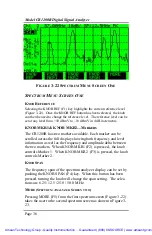
User Table. Pushing the EXIT (F5) function key  (EXIT) or the 
ESC (Escape) key takes the operator up one level to the 

Channel 

Tables 

menu. 

  F

IGURE

 3-10 


E

DIT

 C

HANNEL

 T

ABLE


The 

Edit Channel 

screen allows the operator to select the modulation for-

mat and related parameters for each channel on the network.   Access the 

Edit Channel  

screen  (Figure 3-10)  from the 

Main Setup menu (Figure 

3-6).  P

osition the cursor so that it highlights 

Chan. Tables 

and press  EN-

TER (F1)  to enter the 

Channel Tables 

screen (Figure 3-8).  Push  EDIT 

(F2)  to begin editing channels.  Channel 2 comes up as the default chan-
nel.  Utilizing the tuning knob,  select the channels you wish to edit.  
Pressing  NEXT FIELD (F1) will move the cursor through each of the 
parameters to be set. PREV FIELD (F2) will move the cursor in the oppo-
site direction.  The defaults parameters are: 


            Modulation:                                                               NTSC 

            Frequency Offset:                                                 00.0 kHz 

            Active:                                                                            Yes 

            Auto Test:                                                                      Yes 

            *Invert Spectrum:                                                            No  

            *Symbol Rate:                             5.059641Mhz  (keypad) 

            *Use FEC info:                                                             YES 

                *M

EAS

. B

ANDWIDTH

:             5.312500MHZ (

KEYPAD

)        * 

Artisan Technology Group - Quality Instrumentation ... Guaranteed | (888) 88-SOURCE | www.artisantg.com

Summary of Contents for Hukk CR1200R

Page 1: ...l service in house repair center WE BUY USED EQUIPMENT Sell your excess underutilized and idle used equipment We also offer credit for buy backs and trade ins www artisantg com WeBuyEquipment REMOTE INSPECTION Remotely inspect equipment before purchasing with our interactive website at www instraview com LOOKING FOR MORE INFORMATION Visit us on the web at www artisantg com for more information on ...

Page 2: ... Overview 7 Instrument Overview 8 Front Panel Drawing 9 Connectors controls and displays 10 CHAPTER 2 PREPARATION FOR USE Instructions for unpacking inspecting and preparing the CR1200R for use Introduction 13 Unpacking and initial inspection 13 Shipment Contents 13 Operator Maintenance 14 Power Requirements 14 Artisan Technology Group Quality Instrumentation Guaranteed 888 88 SOURCE www artisantg...

Page 3: ...s 15 The Escape button 15 Checking system status 16 I O Connections 17 RF Input 17 AC Adapter 17 Connecting to a Serial Printer 18 Connecting to a Computer Serial Port 18 Setup Button functions 19 System 19 Set the Contrast 19 Speaker on off 20 Backlight control 20 Automatic Power Down 20 Set time 20 Set date 20 Serial Port Speed 20 Serial Format 21 Site Name 21 Channel Table Setup 22 Artisan Tech...

Page 4: ...ement BW 26 Channel Presets 26 Insert and Delete Channels 27 Level Mode 28 Tuning 29 Channel Tuning 29 Frequency Tuning 29 Five Channel Presets 30 Force NTSC DIGITAL Modulation Change 30 Measurement BW change 31 Scan Mode 31 Knob Ref 32 Knob Marker 32 Knob Scale 33 Log Data 33 Data Log 33 View Test 34 Artisan Technology Group Quality Instrumentation Guaranteed 888 88 SOURCE www artisantg com ...

Page 5: ...verage Peak detector 37 Max Hold 37 Misc Setups 38 Resolution BW 38 Video BW 38 Averages 39 Measurement BW 39 Spectrum menu screen three 39 Zero Span mode 40 Time Domain 40 Knob Trigger Threshold 42 Trigger Setup 42 Sweep mode 42 Edge trigger 42 Averaging 42 Frequency domain 43 Run Stop 43 Knob Reference 44 Artisan Technology Group Quality Instrumentation Guaranteed 888 88 SOURCE www artisantg com...

Page 6: ... Log Errored or Severely Err Seconds 50 Auto Diagnosis 50 Digital Measurements 51 Restart 51 Zoom Mode 52 Log on off 52 Adaptive Equalizer 53 High Pass Filter 54 AUTOMATIC TESTING 55 RUN ANALOG RUN DIGITAL 55 Auto Test Results 56 Analog Results 56 Digital Results 56 24 Hr FCC Tests 58 Enter Start Time 58 Enter Site Name 58 Artisan Technology Group Quality Instrumentation Guaranteed 888 88 SOURCE w...

Page 7: ...s 63 CHAPTER 5 OPTIONS AND ACCESSORIES Options 65 Accessories 65 CHAPTER 6 MAINTENANCE AND SERVICE MAINTENANCE 66 Battery Replacement 66 Cleaning 66 TROUBLESHOOTING 67 SERVICE 67 Warranty 67 Returning Equipment 68 CONTACT Sunrise Hukk Division 68 Artisan Technology Group Quality Instrumentation Guaranteed 888 88 SOURCE www artisantg com ...

Page 8: ...orms error detection on the live program data stream In addition the CR1200R performs analog tests on NTSC HRC and IRC signals providing video and audio measurements of these signals The return path option allows a fully functioned spectrum ana lyzer display of both the forward and return path The zero span analyzer function allows accurate measurements of return path TDMA QPSK signals MANUAL OVER...

Page 9: ... identification and measurement values The controls are pres sure sensitive keypad switches with tactile feedback A 75 ohm F connector accepts the RF input signal A female DB9 connec tor interfaces to a computer port A DC input accepts power from the supplied AC adapter or a 12 volt DC source The CR1200R is packaged in a rugged weatherized hard plastic case Artisan Technology Group Quality Instrum...

Page 10: ...Sunrise Telecom Hukk Division Page 9 Figure 2 1 Artisan Technology Group Quality Instrumentation Guaranteed 888 88 SOURCE www artisantg com ...

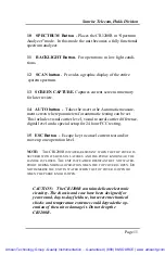
Page 11: ...tion Keys F1 through F5 Soft keys to perform vari ous tests and setups per the screen display 6 DIGITAL Button Places the CR1200R in Digital mode This mode is used for performing digital tests including bit error rate modulation error rate adaptive equalizer stress and constella tion 7 POWER button Turns unit on off 8 LEVEL Button Places the CR1200R in Level mode In this mode the unit becomes a fu...

Page 12: ...or 24 hour FCC testing 15 ESC Button Escape key to cancel current test and or move up one operation level NOTE THE CR1200R IS WATER RESISTANT WHEN THE TOP COVER IS SECURED WITH ITS BUILT IN LATCHES AND THE PURGE KNOB NEAR THE HANDLE IS CLOSED THE UNIT IS WEATHER RESISTANT BUT NOT WATER PROOF DURING NORMAL OPERATION WHEN THE TOP COVER IS OPEN DO NOT IMMERSE THE UNIT IN WATER WHEN THE TOP COVER IS O...

Page 13: ...Model CR1200R Digital Signal Analyzer Page 12 This Page Reserved for Future Use Artisan Technology Group Quality Instrumentation Guaranteed 888 88 SOURCE www artisantg com ...

Page 14: ...rial is damaged check the contents of the shipment for completeness and check the me chanical and electrical condition of the CR1200R and accessories Notify Sunrise Telecom Hukk Division if the contents are incom plete if there is mechanical damage or defect or if the CR1200R does not pass its internal self test procedure If the shipping con tainer is damaged keep the container and packing materia...

Page 15: ... AND THE PURGE KNOB NEAR THE HANDLE IS CLOSED THE UNIT IS WEATHER RESISTANT BUT NOT WATER PROOF DURING NORMAL OPERATION WHEN THE TOP COVER IS OPEN DO NOT IMMERSE THE UNIT IN WATER WHEN THE TOP COVER IS OPEN OR WHEN THE PURGE KNOB IS OPEN CAUTION The CR1200R contains delicate electronic circuitry The chassis and case have been designed for year round day to day field use but severe mechanical shock...

Page 16: ...1200R is designed to be easy to operate All of the upper level functions are available by pushing one button and all key tests can be performed by the CR1200R by pushing on average only 2 buttons After any upper level test button the Digital key for instance is pushed the function keys F1 through F5 take the operator to the various tests that are available THE ESCAPE BUTTON While any tests are run...

Page 17: ...the SETUP button The Main Setup screen will appear as shown in Figure 3 1 Utilizing the tuning knob move the cursor until it highlights System Status then press ENTER The screen shown in Figure 3 2 will appear FIGURE 3 2 Artisan Technology Group Quality Instrumentation Guaranteed 888 88 SOURCE www artisantg com ...

Page 18: ...upplied with the CR1200R This adapter produces 15 5 VDC with a 3 4A rating Plug the adapter into the CR1200R before attaching it to the AC source See Chap ter 5 Options and Accessories for additional information The CR1200R can be used for measurements while powered by the AC adapter However the AC adapter will charge the CR1200R battery only while the CR1200R is powered off FIGURE 3 3 Do not use ...

Page 19: ...ions Equipment The output rate is configur able using the setup screen with 8 bit words one stop bit and no parity The CR1200R does not perform flow control The printer must be able to print at the configured rate without overflow CONNECT TO A COMPUTER SERIAL PORT Use a DB9 straight through cable to connect the RS 232 connector on the CR1200R to the serial port of a computer You must have communic...

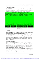
Page 20: ...and turn the tuning knob to change the settings Be sure to press the SAVE F4 key to save your settings before exiting via the EXIT F5 key SET THE CONTRAST While on the SYSTEM SETUP screen Figure 3 5 use the F1 and F2 keys to position the cursor over Contrast Use the knob to ad just the contrast from 0 very dark to 100 very light Adjust contrast to the operator s preference Make sure you save your ...

Page 21: ... set to ALWAYS ON as this will discharge the internal battery sooner than using the CR1200R without the backlight AUTOMATIC POWER DOWN Setting this field to ON will cause the CR1200R to power itself down after approximately three minutes of inactivity on the key pad The unit will not power down automatically if locked to a QAM signal data logging or if the AC adapter is plugged in SET THE TIME Use...

Page 22: ...1 stop bit 8 n 1 Other formats are available use the knob to switch between them FIGURE 3 6 SITE NAME From the Main Setup screen Figure 3 6 utilize the tuning knob to move the cursor over Site Name and press ENTER The Site Name Edit screen will appear as shown in Figure 3 7 Enter the FIGURE 3 7 Artisan Technology Group Quality Instrumentation Guaranteed 888 88 SOURCE www artisantg com ...

Page 23: ...200R Digital Signal Analyzer is designed to operate on Standard HRC or IRC Cable TV networks In addition there are 3 user programmable plans that can be stored in memory This al lows the CR1200R to be used on separate networks with different channel plans without reprogramming the CR1200R each time Due to the nature of digital signal testing it is highly recom mended that operator program a custom...

Page 24: ... enter the Channel Tables menu Figure 3 8 FIGURE 3 9 In the Channel Tables menu turn the tuning knob clockwise or counterclockwise to highlight the channel plan type currently in use in your system Standard HRC or IRC Once the channel plan type is selected pushing the F3 function key selects the highlighted plan to be copied and takes the user to the Copy Chan nel Table screen Figure 3 9 Once the ...

Page 25: ...s Chan Tables and press EN TER F1 to enter the Channel Tables screen Figure 3 8 Push EDIT F2 to begin editing channels Channel 2 comes up as the default chan nel Utilizing the tuning knob select the channels you wish to edit Pressing NEXT FIELD F1 will move the cursor through each of the parameters to be set PREV FIELD F2 will move the cursor in the oppo site direction The defaults parameters are ...

Page 26: ...cy or aeronautical frequencies are sometimes offset to avoid potential interference ACTIVE Yes The channel is active both when the tuning knob is used to while making a channel selection and during system scans No The channel will not appear during system scans and tuning knob channel selection Channels will need to be manually en tered AUTOTEST Yes The channel is active during all Auto Test funct...

Page 27: ...r to measure a signal other than Annex B NOTE IF MEASURING A SIGNAL THAT IS NOT ANNEX B THE CONSTEL LATION AND MER VALUES CAN STILL BE OBTAINED BY SETTING THIS FIELD TO NO MEASUREMENT BANDWIDTH This mode allows the user to set a measurement bandwidth for digital channels with a bandwidth other than the 6 MHz standard default To change the Measurement Bandwidth MBW enter the bandwidth in MHz utiliz...

Page 28: ...nsert additional channels or to delete channels from the existing channel plan INSERT CHANNEL From the EDIT CHANNEL menu press MORE F5 and select INSET CHANNEL F1 The screen shown in Figure 3 12 will be displayed with the Frequency highlighted Enter the frequency on the numeric keypad and press ENTER on the numeric keypad Use the NEXT FIELD F1 and PREV FIELD F2 function keys to highlight the Chann...

Page 29: ...channel will have to INSERTED in order to restore it to the channel plan LEVEL BUTTON Pushing the front panel LEVEL button on the CR1200R opens the main signal level test screen Figure 3 13 Channel number frequency and modulation formats are displayed at the top of the screen On the right is a numerical indication of the video and au dio level of the channel being tested On the left is a graphical...

Page 30: ...he alpha numeric keypad to enter the channel number followed by the CHAN key The CH a the top of the display will indicate the currently tuned channel with the appropriate frequency next to it Frequency Tuning is accomplished by pressing the FREQ MHz key and using the tuning knob to sequence through the channels Only frequencies programmed into the channel table may be selected To tune to frequenc...

Page 31: ...vision and the knob can be used to change the reference level so that the levels are not full screen The ESCAPE key ends the test and takes the operator up to the main LEVEL screen FIGURE 3 14 FORCE NTSC DIGITAL MODULATION CHANGE From the LEVEL main screen the user can use the FORCE NTSC DIGITAL F4 function key to force the modulation measurement type to be changed The two choices are FORCE NTSC a...

Page 32: ...rror message Caution When changing the MBW ensure that you have the correct bandwidth information for the signal un der test FIGURE 3 15 The typical measurement band width for digital channels is 5 312500 MHz Changing MBW does not change the resolution bandwidth of the unit but compensates the measurement and adjusts the displayed measurement value based on the desired bandwidth Only in the Averag...

Page 33: ...NOB REF The reference level of the scan can be changed by hitting the KNOB REF F1 button and then turning the tuning knob until the desired reference level appears on the Marker Screen Note that the scan takes approximately 10 seconds The new levels are not reflected in the display until a new measurement is taken for that channel A new scan is started when the knob is turned KNOB MARKER The posit...

Page 34: ...ve this scan and store the results in the data log The data log entry will be referenced to the site name currently stored in the setup screen When the scan is complete the log shuts off automatically and the LOG DATA soft key returns to normal The results of the log can be viewed via the DATALOG selection in the SETUP menu screen FIGURE 3 17 DATA LOG The information stored in the Data Log can be ...

Page 35: ... To view stored data use the tuning knob to scroll through the menu to select the set of data that you want to display Use the NEXT SET F1 or PREV SET F2 keys to page through addi tional pages of stored data To view the highlighted data press the VIEW TEST F3 key The stored screen data will be displayed just as it was stored The tuning knob will be active in modes that have a marker to allow the u...

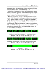
Page 36: ... left side of the screen from top to bottom shows Reference Level Marker 1 frequency and level Marker 2 frequency and level Delta frequency and level difference between markers and whether the analyzer is utilizing the peak or average detector When in SPECTRUM analyzer mode hitting the MORE key will toggle the user through each of the Spectrum menu screens and attached soft keys listed below Knob ...

Page 37: ...showing both frequency and level information as well as the frequency and amplitude delta between the two markers When KNOB MKR1 F2 is pressed the knob controls Marker 1 When KNOB MKR2 F3 is pressed the knob controls Marker 2 KNOB SPAN The frequency span of the spectrum analyzer display can be set by pushing the KNOB SPAN F4 key When this button has been pressed turning the knob will change the sp...

Page 38: ...or currently in use is displayed in the top right portion of the screen PK is displayed for Peak Detector used on normal NTSC signals and AV is dis played for Average Detector used on Digital signals HOLD ON Selecting the HOLD ON F3 key puts the analyzer in maximum hold or peak hold mode As the analyzer sweeps through the fre quency range selected the highest level at any given frequency is rememb...

Page 39: ...IDTH The resolution bandwidth may only be adjusted in the ZERO SPAN mode To change the resolution bandwidth press the NEXT FIELD F1 or the PREV FIELD F2 button until RES BW is highlighted Turning the knob will toggle between 300 KHz and 2 MHz Press SAVE F4 to go back to the previous screen and use the new settings Press ESC to return and use the previous settings VIDEO BANDWIDTH To change the Vide...

Page 40: ...esired MBW can also be entered on the keypad by entering the desired number in MHz followed by either the ENTER or FREQ MHZ keys The measurement bandwidth ranges from 1 Hz to 6 MHz Changing MBW does not change the resolution bandwidth of the unit but compensates the measurement and adjusts the displayed measurement value based on the desired bandwidth SAVE Make sure you save your changes before ex...

Page 41: ...3 Figure 3 25 puts the CR1200R s spectrum analyzer in the zero span mode In this mode the horizontal axis of the screen changes from the frequency domain to the time domain Figure 3 26 FIGURE 3 26 When in ZERO SPAN mode selecting the MORE key will toggle the user through each of the ZERO SPAN menu screens and func tion soft keys listed below Artisan Technology Group Quality Instrumentation Guarant...

Page 42: ...e screen shown in Figure 3 26 Pressing the MORE F5 key from this screen will take the user to the additional function keys Knob Ref Knob Mkr1 Knob Mkr2 Knob Span and More figure 3 28 The analyzer remains in ZERO SPAN mode until the FREQ DOMAIN F3 soft key is depressed As the MORE F5 key of each ZERO SPAN menu is depressed the screens toggle between the three ZERO SPAN menu screens FIGURE 3 29 ZERO...

Page 43: ...e quences through the parameter settings Press SAVE to go back to the previous screen and use the new parameters or EXIT to return to the previous screen using the old parameters Mode Sweep This allows the user to select the desired sweep mode Use the tuning knob to sequence through the selections CONTINU OUS DISABLED and SINGLE Press SAVE to go back to the previous screen and use the new settings...

Page 44: ... the previous screen and use the new parameters or EXIT to return to the previous screen using the old parameters FREQ DOMAIN EXIT ZERO SPAN Pressing the FREQ DOMAIN F3 key while in the ZERO SPAN mode figure 3 31 turns off zero span taking the analyzer back to the frequency domain RUN STOP Selecting the RUN STOP F4 key temporarily stops the sweep Note that when the function key displays STOP that ...

Page 45: ...ta between the two mark ers When KNOB MKR1 F2 is pressed the knob controls Marker 1 When KNOB MKR2 F3 is pressed the knob controls Marker 2 The display area on the left side of the screen provides the measure ment results for the markers KNOB SPAN The time span is displayed at the top of the screen The span may be set by pushing the KNOB SPAN F4 key When this button has been pressed turning the kn...

Page 46: ...M channel The unit will not lock to a 64QAM signal if the channel table is set for 256QAM and vise versa The channel tables must be properly pro grammed FIGURE 3 32 FORCE QAM MODULATION If the CR1200R is tuned to a digital signal not programmed in the current channel plan the CR1200R opens up the force modulation screen as shown in Figure 3 29 This allows the operator to quickly force the CR1200R ...

Page 47: ...ent measurements They are Modulation Error Ratio Pre Forward Error Correction error ratio Pre FEC Post Forward Error Correction error ratio Post FEC and the Constellation Dis play which includes an Auto Diagnosis function At the top of the screen is the channel number and the center fre quency of the digital channel being tested The test results are found along the right hand side of the screen al...

Page 48: ... the digital carrier and locks on it the FEC test the Modulation Error Ratio test and the Constellation test begin The Elapsed test time counter starts at the same time MER MODULATION ERROR RATIO The Modulation error ratio MER the digital equivalent of signal to noise is the measurement of the demodulated digital signal in the noise of its environment In the CR1200R this measurement is based on co...

Page 49: ...e Post FEC remains at zero A severely errored second is a point in time when the FEC codes are unable to correct all errors received and a possible impairment is passed through the set top box to a subscriber s television set CONSTELLATION The Constellation is a graphic display of a QAM modulated digital signal It can be used to show impairments in a network whether they come from noise spikes or ...

Page 50: ... screen press the SETUP button on the front panel of the unit The Main Setup screen Figure 3 35 will appear FIGURE 3 35 Rotate the tuning knob until DIGITAL is highlighted then press the EN TER F1 key The Screen shown in figure 3 36 will appear Utilizing the NEXT FIELD and PREV FIELD keys choose which of the three parameters you would like to change FIGURE 3 36 Artisan Technology Group Quality Ins...

Page 51: ...ELL Press SAVE to go back to the previous screen and use the new settings or EXIT to return to the previous screen using the old set tings LOG ERRORED OR SEVERELY ERRORED SECONDS The Digital setup screen also allows the user to determine whether or not Errored Seconds or Severely Errored Seconds will be con sidered an error event to be automatically recorded in the data log FIGURE 3 37 AUTO DIAGNO...

Page 52: ...esented on sequential screens include RESTART ZOOM SELECT LOG ON OFF EQUALIZER and HIPASS ON OFF RESTART Pushing the RESTART F1 function key at any time while in the first Digital screen Figure 3 37 will cause the CR1200R to re lock on the digital signal and reset all counters to zero Errored Seconds Severely Errored Seconds and the Elapsed Time MORE Selecting MORE at any time while in the first D...

Page 53: ...igure 3 39 shows the ZOOM mode screen The EXIT F5 key returns the user to the second digital screen Figure 3 31 FIGURE 3 39 MORE Selecting MORE at any time will bring up the next digital screen as shown in Figure 3 40 LOG ON OFF Selecting the LOG ON F4 function will write all error events to the Data Log This is particularly effective for intermittent prob lems that occur at random intervals See F...

Page 54: ...n Figure 3 41 ADAPTIVE EQUALIZER The adaptive equalizer is a feature of the digital demodulator that looks at reflections on a network and attempts to minimize their influence on a digital bit stream FIGURE 3 41 The Adaptive Equalizer screen Fig 3 41 is accessed from the Artisan Technology Group Quality Instrumentation Guaranteed 888 88 SOURCE www artisantg com ...

Page 55: ...en MORE Selecting MORE from the current Digital menu screen 3 41 will bring up the HIGH PASS Filter mode HIGH PASS FILTER Pressing the MORE key from the equalizer screen allows the user to implement a special high pass filter in the CR1200R This filter is designed to be utilized in conditions where the network is showing reverse tilt at levels that are higher than normal 8 db of reverse tilt For e...

Page 56: ...TUP with pass fail criteria for evaluating the AUTO test Prior to initializing an AUTO TEST use the tun ing knob to select the Location for the AUTO TEST The Location will be stored along with the data and SITE NAME if the AUTO TEST is STORED The RUN ANALOG RUN DIGITAL and START 24 HR tests are all based on the current channel plan programmed into the Channel Tables See the SETUP operation and Fig...

Page 57: ...wn in Figure 3 44 is automatically updated to the AUTO TEST RESULTS screen This screen provides the test results for each channel in the channel ta ble used for the measurements The initial screen displays only those channels which failed according to the SETUP criteria for that site ANALOG RSULTS The AUTO TEST RESULTS screen following an ANALOG test displays the Location and Site Name the list of...

Page 58: ...tion and Site Name the list of Channel numbers the MER PEEBER PSTBER LEVEL and DIAGNOSIS the number of channels Tested the number that Passed and the num ber that Failed according to the SETUP criteria for the Location and the test in process Figure 3 45 FIGURE 3 45 Artisan Technology Group Quality Instrumentation Guaranteed 888 88 SOURCE www artisantg com ...

Page 59: ...200R Digital Signal analyzer will perform 24 hour level testing as required by the Federal Communications Commission To begin the FCC testing press the START 24 HR TEST F3 soft key The FCC DATALOG screen will appear as shown in Figure 3 45 The FCC Testing Data Log screen Figure 3 46 prompts the operator to enter the time the test should begin and the site location where the test is taking place FI...

Page 60: ...NAME WILL REMAIN THE SYSTEM DEFAULT UNTIL CHANGED EITHER AS IN FIGURE 3 36 OR AS DESCRIBED IN THE SYSTEM SETUP SECTION OF THE MANUAL SEE FIGURE 3 6 STARTING THE TEST Pressing the START TEST F3 soft key from the FCC DATA LOG SETUP screen Figure 3 46 will begin the test process immediately Otherwise the CR1200R will wait for the programmed start time be fore beginning the test If the test is started...

Page 61: ...he tuning knob sequences through the parameter settings Press SAVE to go back to the previous screen and use the new parameters or EXIT to return to the previous screen using the old parameters REMOTE SOFTWARE Test results can be viewed on the CR1200R screen or downloaded to a computer utilizing the CR1200 remote software which can be downloaded at no charge at www hukk com The software is designe...

Page 62: ...ough interface cable will work with the Remote Software The cable connects between your com puter s communications port and the CR1200R DB 9 interface con nector A pin out of the cable is shown in figure 3 50 Artisan Technology Group Quality Instrumentation Guaranteed 888 88 SOURCE www artisantg com ...

Page 63: ... that similar cables are used for computer interface with a different pin out Null Modem cables appear to be identical but have the connections to pin 2 and 3 crossed in the cable Artisan Technology Group Quality Instrumentation Guaranteed 888 88 SOURCE www artisantg com ...

Page 64: ...EL Accuracy 2 0 dB 25º C Average Detector GRAPHIC DISPLAYS Constellation I Q display of 64 or 256 QAM signal Equalizer Display of adaptive equalizer taps BER Pre and Post FEC Range 1 0 x 10 9 to 9 0 x 10 3 FEC Lock Loss Lock indication Errored Seconds Numerical count of errored seconds Severely Errored Seconds Numerical Count of SEC ANALOG SIGNAL ANALYSIS Modulation Type VSB NTSC Operation Range 2...

Page 65: ...3 hours nominal ADDITIONAL FEATURES GENERAL Display LCD with backlight Frequency Plans NTSC STD IRC HRC Power Reduction Auto unit shut down Elapsed Time hr min sec Store Recall All data and graphs Printouts RS 232 to computer Hukk Engineering reserves the right to change any or all specifications without notice All digital measurements are for individual channels with power levels be tween 20 and ...

Page 66: ...tween 5 and 42 MHz The combination of the return path capability and zero span testing creates a powerful tool for measuring return path TDMA signals such as the 16 QAM and QPSK signals used by both cable and telephony modems For return path operation see Chapter 3 Operation ACCESSORIES The CR1200R comes with the following standard accessories Manual and Training CD ROM AC power adaptor Input 100 ...

Page 67: ...by charge voltage on the battery to maximize its shelf and operating life NOTE USE ONLY THE SUPPLIED AC ADAPTER TO RECHARGE THE CR1200 INCORRECT POLARITY OR VOLTAGE COULD DAMAGE THE CR1200 OR INTERNAL BATTERY Only Replace Battery with Hukk part number 120 10789 001 9 Cell Nimh Battery Pack Used batteries should not be discarded Dispose of battery through appropriate recycling program CLEANING Clea...

Page 68: ...ta from the optional log memory the internal lithium battery may have failed Call Sunrise Telecom Hukk Division for service If the CR1200R fails to detect QAM carriers or if the unit won t lock to carriers when using the force modulation mode check the RF input power level The CR1200 can be overloaded by ex cess power at the input The resulting signal distortion impairs the ability of the CR1200 t...

Page 69: ...ficient to avoid damage in transit Sunrise Telecom Hukk Division is not liable for damage that occurs during shipping Return equipment to Sunrise Tele com Hukk Division with shipping prepaid Attach the following information to all equipment returned for repair Owner s name and address A list of the equipment being returned and the serial number A detailed description of the problem or service requ...

Page 70: ...l service in house repair center WE BUY USED EQUIPMENT Sell your excess underutilized and idle used equipment We also offer credit for buy backs and trade ins www artisantg com WeBuyEquipment REMOTE INSPECTION Remotely inspect equipment before purchasing with our interactive website at www instraview com LOOKING FOR MORE INFORMATION Visit us on the web at www artisantg com for more information on ...

Reviews: