www.sunrotor.com
Page 16
door providing easy access to adjust the settings, and the ability to see the indicator lights at a glance.
The controller comes in three sizes: 50V, 100V, and 200V DC input tolerance limits. The size will be
determined by the solar array and pump configuration.
There are other models available that offer fewer features than the standard controller. The overall
function is the same, and the wiring is similar. If any controller other than the SRC-M50T, SRC-
M100T, or SRC-M200T is purchased, please contact your Authorized SunRotor
®
Dealer or the
SunRotor
®
Technical Services Team for any information not provided within this installation guide.
The ability to use both AC (generator, power lines, etc.) and DC (solar array, batteries) is available
with additional equipment. A Power Pack is necessary if both AC and DC input are desired. If a
battery back-up is required for times of need, such as when it is hazy or dark, a charge controller is
needed. No information is provided within this installation guide on configuring and installing these
accessories; however, they may be available on the SunRotor
®
Solar Products website under the
product information or the Downloads page. If it cannot be found there, please contact the
SunRotor
®
Technical Services Team at 1(866) 246-7652.
6.2
L
OCATING AND
M
OUNTING THE
C
ONTROLLER
C
AUTION
:
Direct sunlight can reduce the life of the controller.
Mount the controller so it is shaded from the mid-day sun. The easiest location is under the PV array.
If necessary, mount the controller inside a shelter or make a sheet-metal shade for it. If the solar array
is a substantial distance from the wellhead, it is preferable to place the controller closer to the pump.
If the solar array is nearby, it is recommended to mount the controller box to the pipe below the solar
array. Securely fasten the controller to the opposing side of the solar panels. The solar panels will
keep the controller out of the direct sunlight, increasing its efficiency and life. Controller mounting
hardware may be purchased from your Authorized SunRotor
®
Dealer, or built using materials
commonly available from electrical supply stores.
6.3
I
NDICATOR
L
IGHTS
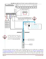
The indicator lights located on the upper half of the controller display the status of the pumping
system (See
Figure 6-1 SunRotor
®
Controller Design
)
. Below is an explanation of each indicator light
and its function.
SYS
(
Solid Green
): This indicator light will illuminate whenever the switch is in the
on
position and
the power is available to the controller.
Pump
(
Solid Green
): This indicates that power is being applied to the pump. This indicator will
illuminate 20-30 seconds after the system has been switched on as long as there is adequate power
available and all water level sensors are reading normal.
Summary of Contents for Solar Pump
Page 1: ...SunRotor Solar Pump Installation and Resource Manual...
Page 36: ......


