Page 23
www.sunrotor.com
or more. If setting the pump less than 150 ft, consider using the Hand Installation (See
Section 8.3
Hand Installation
). It may take less time to drop or pull the pump by hand than it does to use a pump
service truck, especially in a difficult location.
8.3
H
AND
I
NSTALLATION
W
ARNING
:
Hand Installation can be hazardous. There are potential hazards in handling
any heavy mechanical assembly. If there are any doubts about the ability to
SAFELY
install
by hand, please hire a professional pump installer. Any injury or damage sustained by
using this method will be the sole responsibility of the installer.
C
AUTION
:
D
O NOT
use a winch to install or remove the pump. To remove the pump, pull
up the rope, cable, and pipe simultaneously; otherwise, there is a risk of having the
flexible pipe and cables sag down and jam between the pump and casing. This can cause
damage or loss of equipment, and potentially, even the loss of the well itself.
C
AUTION
:
D
O NOT
use a vehicle to pull the pump. To remove a pump installed by hand,
use
HAND POWER
only! During removal, the pump can catch on joints or edges in the
casing. Any problems along the way will be felt as you pull by hand. Any damage for
neglecting these warnings will void the warranty.
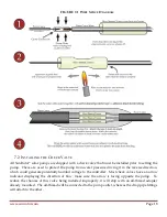
Lay a barrel (metal oil drum or similar rounded object) next to the wellhead. Run the pipe, cable, and
rope over the round surface, to ease the downward bend and to prevent scraping against the edge of
the casing. Wear leather gloves.
Lower the pump slowly and carefully. To verify the static water level, assign a helper to listen
carefully for a splash as the pump hits the water. You can then determine the static level by
measuring the length of remaining pipe above ground.
The in-well assembly should hang with the weight on the pipe. Tie the rope securely, inside the
casing. Do not attach the rope to the removable cap of the casing, or it will prevent easy removal.
C
AUTION
:
Do not support or pull the pump by the safety rope alone.
Pulling only the rope can cause the cable and pipe to sag and to jam in the casing. It must
be grabbed by the pipe and cable along with the rope. Wear tough leather work gloves.
8.4
R
UNNING THE
C
ABLES
Run the pump and low water sensor cables through well seal assembly to the specified grommets on
the bottom of the controller (See
Figure 6-1 SunRotor
®
Controller Design
).
If using flexible conduit, attach one end to the top of the well seal assembly and run the wires though
it. Place the connector on the controller side of the flexible conduit and run the cable trough and into
the controller and attach the connector to the controller.
Summary of Contents for Solar Pump
Page 1: ...SunRotor Solar Pump Installation and Resource Manual...
Page 36: ......


