www.sunrotor.com
Page 24
9
W
IRING THE
S
YSTEM
9.1
E
LECTRICAL
W
ARNINGS
A
TTENTION
:
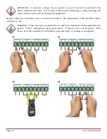
Wiring the panels in the wrong configuration (series or parallel) can send
excessive voltage and damage the controller. Be confident in understanding the system’s
wiring configuration and voltage limitations (See
Figure 5-3 Solar Panel Wiring Diagram
for
examples) prior to connecting the solar array to the controller. Additionally, it is
recommended that the panels are covered or shaded when connecting them to the
controller to prevent damaging the equipment. Any damage caused by ignoring these
warnings will not be covered under the warranty.
W
ARNING
:
There are live electrical currents with high voltages present that can cause
SERIOUS INJURY OR DEATH
. Please use extra precautions and thoroughly read through this
section prior to wiring the system. Follow all appropriate electrical codes. If unsure, hire
a professional. Solar Power & Pump Company is not liable for personal injury or damage
to the equipment.
Please read through this entire section prior to wiring the system. If any questions or concerns on
safety or correct wiring are present this process, please contact your Authorized SunRotor
®
Dealer or
the SunRotor
®
Technical Services Team at 1(866) 246-7652.
9.2
W
IRING THE
C
ONTROLLER
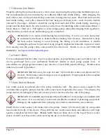
Run the pump and sensor cables through the bottom of the controller. The use of spade connectors at
the end of your wires is recommended for easy maintenance and repairs in the future.
A
TTENTION
:
Installing a low water sensor is
HIGHLY
recommended. This device sends a
signal to the controller—which in turn shuts the pump off—if water in the well drops
below the sensor set depth. This protects the pump from running dry.
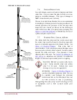
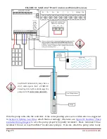
As shown in
Figure 9-1 SunRotor
®
Pump Controller Wiring Diagram
, attach the two wires to
the
COM1
and
WH
terminals. If no low water sensor is used, a jumper is required for the pump to
run.
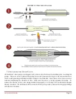
Wire or cable used for connecting the
Tank Full Switch
should be two-conductor shielded
instrumentation cable. The use of this cable helps prevent potential lightning damage normally
associated with a lengthy string of cable. Additionally, a ground wire is included in this type of
cable. Similar to the low water sensor, the wires need to be attached to
COM2
and
TH
terminals.
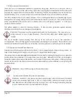
The ground wire should be attached to the nearest back plate mounting screw (See
Figure 9-1
SunRotor
®
Pump Controller Wiring Diagram
).
Summary of Contents for Solar Pump
Page 1: ...SunRotor Solar Pump Installation and Resource Manual...
Page 36: ......


