www.sunrotor.com
Page 26
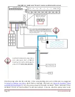
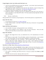
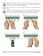
of the numbered terminals, and power up the controller to test the pump direction. If no water is
pumped, or if there is suction on the outlet pipe (this only applies to helical rotor pumps—centrifugal
pumps will produce about ¼
th
flow rate), turn off the power and switch any two of the three pump
cable wires. This will reverse the pump rotation. Turn the pump back on, and confirm water flows
at the proper rate from the pipe. If no water flows after switching two wires, turn the power off and
contact either your Authorized SunRotor
®
Dealer or the SunRotor
®
Technical Services Team at 1(866)
246-7652.
9.3
W
IRING
P
OWER TO THE
C
ONTROLLER
The SunRotor
®
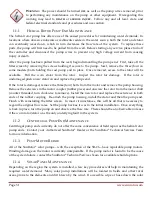
controller comes equipped with MC-4 cable connectors already attached to the proper
controller terminals. Ensure the solar array wiring configuration and voltage before attaching the
connectors (See
Figure 5-3 Solar Panel Wiring Diagram
). Make sure the controller is set to the
OFF
position and plug the corresponding female and male ends together.
9.4
P
OST
-I
NSTALLATION
T
ESTING
The following tests are recommended after completing the installation.
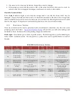
To test the low water sensor, disconnect one wire to open the circuit. Since it is a normally closed
switch, removing one end of the sensor cable or jumper will trigger the circuit logic to turn off the
pump. To test the timer function, set the timer to a low setting: somewhere between 0 and 5 (around
2 ½ minutes). Disconnect the cable and wait for the pump to turn off. After the pump stops,
reconnect the cable. The pump should automatically turn back on after the specified time has passed.
Most tank full float switches are normally open. To test it, jumper between the two tank full
terminals. This will create a closed circuit, and the pump should turn off. Once the jumper is
removed, the pump will restart.
If these tests do not produce the same results, see
Section 10 Troubleshooting
.
Please contact your
Authorized SunRotor
®
Dealer or the SunRotor
®
Technical Service Team directly at 1(866) 246-7652 if
any further information is needed.
10
T
ROUBLESHOOTING
10.1
I
F THE
P
UMP
D
OESN
’
T
R
UN
Most problems are caused by incorrect connections (in a new installation) or bad splices on the pump
cable or low water sensor. The
SYSTEM
light will indicate that the system is switched on. It
indicates that
VOLTAGE
is present, but there may not be sufficient power to start the pump.
System appears dead, no lights showing on the controller:
1.
Is there a disconnect switch or circuit breaker installed on the solar array circuit? Is it off?
2.
Look for disconnected or damaged wires.
3.
Is there any dust or debris on your solar array?
Summary of Contents for Solar Pump
Page 1: ...SunRotor Solar Pump Installation and Resource Manual...
Page 36: ......


