44--22
4.2
Control Board Switch Setting
The Chenille embroidery machine is controlled by the Control Board. It means that ID setting for each board should be
accurate. The following figures show how to set the dip switch ID depending on head, arm and base. If any
communication errors occur, keep in mind the following settings to check the errors.
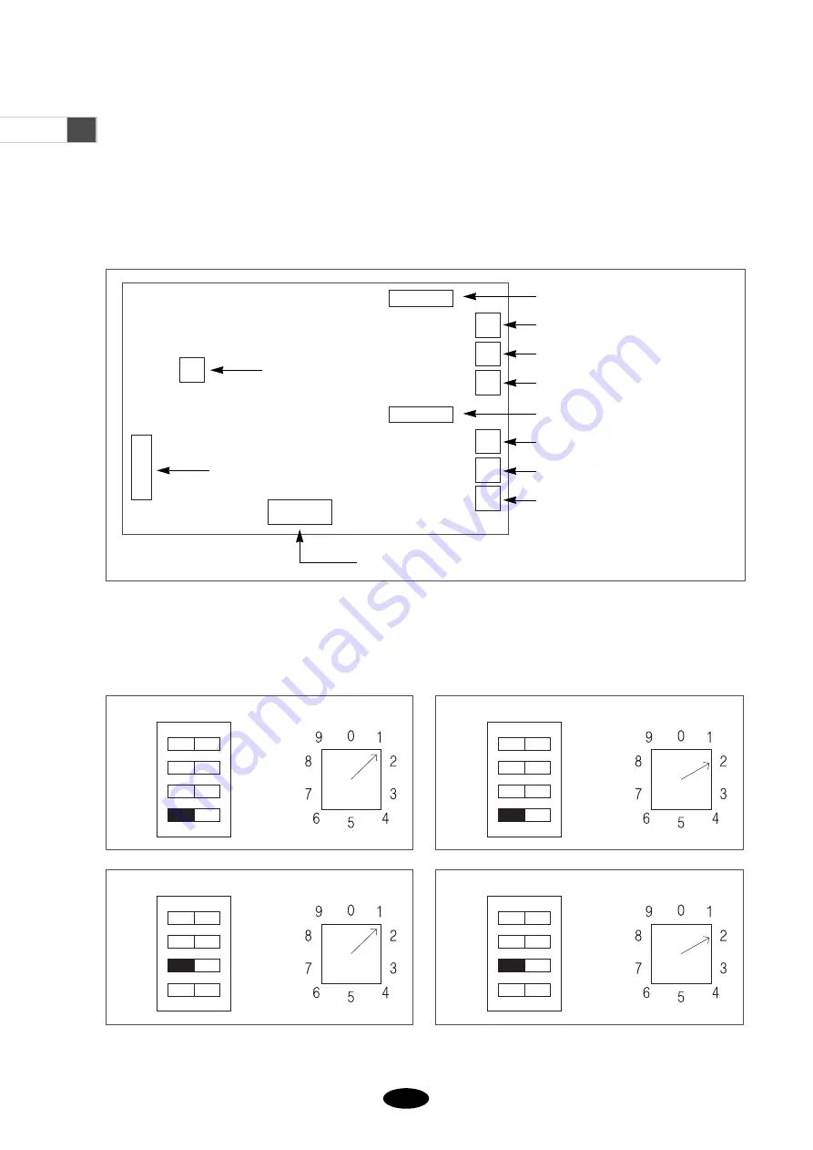
1) Dip Switch (SW2) and Rotary Switch (SW1) Setting for Control Box
- Position of Control Board Switch
[1~2 Head]
[3~4 Head]
[Arm Side]
[Arm Side]
[Base Side]
[Base Side]
Power Input
Dip Switch
SW2
SW1
ON
SW2
SW1
ON
4
3
2
1
4
3
2
1
SW2
SW1
ON
SW2
SW1
ON
4
3
2
1
4
3
2
1
Rotary Switch
SW3
SW4
SW1
SW2
CN14
SW7
SW5
SW6
SW10
SW8
SW9
Step Motor Driver1 Dip Switch
Step Motor Driver1 Rotary Switch1
Step Motor Driver1 Rotary Switch2
Step Motor Driver1 Rotary Switch3
Step Motor Driver2 Dip Switch
Step Motor Driver2 Rotary Switch1
Step Motor Driver2 Rotary Switch2
Step Motor Driver2 Rotary Switch3


