background image

15

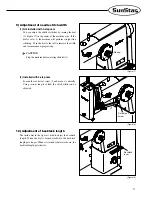
4) How to place the bobbin case

Turn the pulley until the needle bar comes to its highest

position. Bring the bobbin case towards the center stud in

the bottom of the bobbin case. Press the bobbin case until it

makes a clicking sound in the frame. Follow the instructions

carefully to protect the needle in the bobbin frame.

[Figure 11]

5) How to thread the bobbin case

Insert the bobbin case in the bobbin frame. Firmly fix the

bobbin in the frame, push the thread through the hole and

pull it into the lower part of the tension spring and the hole. 

[Figure 12]

6) Lower thread winding and adjustment

(1) Winding the lower thread 

A. The thread should come out through hole 

from the

back of the tension regulating dish 

towards the

front. 

B. The thread should be taken to the bobbin 

and

wound clockwise 5 or 6 times from the bottom. 

C. After pushing lever 

and letting pulley 

touch

the V-belt, run the machine. 

D. If the bobbin winds all the lower thread, pulley 

is

automatically separated from the belt.

(2) Lower thread adjustment 

A. When the lower thread is wound irregularly unscrew

, move it left to right, and tightly screw 

again.

B. The lower thread's winding amount can be adjusted. if

you turn the regulating screw 

clockwise it increases

and if you turn it counterclockwise it decreases.

C. For the lower thread's tension adjustment that winds

the bobbin, if you turn screw 

clockwise it becomes

stronger and if you turn it counterclockwise it

becomes weaker.

[Figure 13]

Summary of Contents for DPK-5

Page 1: ...AD THIS MANUAL BEFORE STARTING USE 2 KEEP THIS MANUAL IN SAFE PLACE FOR REFERENCE WHEN THE MACHINE BREAKS DOWN M MM ME E 0 09 90 09 92 29 9 USER S MANUAL R S Su un nS St ta ar r C CO O L LT TD D DPK 5 Post bed 1 needle lock stitch zigzag sewing machine ...

Page 2: ...e powerful operation enhanced durability and more sophisticated design to meet a number of user s needs 2 Please read this user s manual thoroughly before using the machine Make sure to properly use the machine to enjoy its full performance 3 The specifications of the machine are subject to change aimed to enhance product performance without prior notice 4 This product is designed manufactured and...

Page 3: ...e lifter 12 6 When the unit box is installed 12 7 Cam replacement method 1 step 2 step 3 step optional 13 3 Adjustment of the Machine 1 Inserting the needle 14 2 Pressure adjustment 14 3 How to remove the bobbin case 14 4 How to place the bobbin case 15 5 How to thread the bobbin case 15 6 Lower thread winding and adjustment 15 7 Threading 16 8 How to adjust the thread tension 16 9 Adjustment of n...

Page 4: ... shall be observed strictly Otherwise the user will be killed or suffer severe physical injuries Instructions here must be observed or the user could suffer fatal or severe physical injuries Instructions here should be observed or the user could face physical injuries or mechanical damages Danger The meaning of symbols This symbol means a must not This symbol means a must for safety This symbol me...

Page 5: ...s dysfunction and breakdown are likely to occur depending on the environment in which the machine is installed the following preconditions must be met ⓐ Please unpack the machine package in order Be particularly careful of the nails in the wooden box ⓑ Because machines are apt to be contaminated and corroded by dust and moisture install a climate controller and clean the machines regularly ⓒ Keep ...

Page 6: ...et to off ⓖ Be sure to stop the machine when threading the needle or before checking after sewing ⓗ Do not switch on the power supply with the foot on the pedal ⓘ Do not run the machine when the cooling fan is clogged Be sure to clean the air filter in the control box once a week ⓙ If possible keep the machine away from strong electromagnetic fields like areas around a high frequency welding machi...

Page 7: ... to wait at least 360 seconds before opening this cover after turn off main switch and unplug a power cord 고압 전류에 의해 감전될 수 있으므로 커버를 열 때는 전원을 내리고 전원 플러그를 뽑고 나 서 360초간 기다린 후 여십시오 CAUTION 경 고 Do not operate without finger guard and safety devices Before threading changing bobbin and needle cleaning etc switch off main switch 손가락 보호대와 안전장치 없이 작동하지 마십시오 실 보빈 바늘교환시나 청소전에는 반드시 주전원의 스위치를 꺼 주십시오 CAUTION 경 ...

Page 8: ...RTZ 50 60 Hz 50 60 Hz 50 60 Hz 3 470 motor MODEL PM470 PHASE HERTZ VOLT 4 470 motor controller MODEL PC470 VOLT 1 110V 2 220V MODEL A SUB CLASS 001 Model name Use Max speed Zigzag width Needle Presser bar height Hook Lubrication DPK 5 S DPK 5 C Forheavymaterials Forheavymaterials 2 500 spm 2 500 spm 0 8mm 0 8mm DP 5 11 14 DP 5 11 14 Up to 8mm Vertical large hook 2x Vertical large hook 2x Manual Ma...

Page 9: ...ing type and SEDG 2B for thickness sensing type An essential device when one person is operating multiple sewing machines Has different pedals for acceleration thread trimming presser foot and ascending pedal Types consist of SPDL 1 and EDPL 1 for fixed speed and SPDL 2 and EDPL 2 for variable speed SPF 7 A solenoid operating structure where the presser foot gets lifted automatically with pedal re...

Page 10: ...normal position Using only one hand can lead to severe hand injuries due to the weight of the machine Caution Plug in only after oil supply is finished If the operator mistakenly steps on the pedal with the plug in the machine will start automatically and can cause severe injuries When handling lubricants wear protective glasses or gloves to avoid contact with your eyes or skin Inflammation may be...

Page 11: ...ng by gravity And fasten the fixing nut and then the fixing nut tightly Figure 2 3 Installation of belt cover 1 Fix the belt cover A on the sewing machine body using the fixing screw and the washer 2 Fix the belt cover B on the table using the tapping screw Make sure that the belt does not interfere with the belt cover B Figure 3 Belt cover A Belt cover B ...

Page 12: ... installed The portable synchro is not needed Figure 4 6 When the unit box is installed Needed when the servo motor is installed Fix the unit box bracket to the arm using the socket set screw Place the unit box wiring inside Fix the unit box using the connecting bolt Figure 6 Unit box bracket Unit box 5 How to install the knee lifter The knee lifter replaces manual operation of the presser foot To...

Page 13: ...tep 2 step 3 step optional To change from 1 step to 2 step 3 step or zigzag turn the cam lever counter clockwise and loosen the lever After a different cam is placed turn the cam lever clockwise in full and fix it Figure 7 Cam lever ...

Page 14: ...f the needle closely adhered to the upper side of the stopper hole with the needle groove facing inward Fix the needle with a fixing screw Figure 8 3 How to remove the bobbin case Turn the pulley in a counterclockwise direction to move the thread take up lever to its highest position With your left index and the second finger push up the latch lever of the bobbin case frame to remove the frame wit...

Page 15: ... The thread should come out through hole from the back of the tension regulating dish towards the front B The thread should be taken to the bobbin and wound clockwise 5 or 6 times from the bottom C After pushing lever and letting pulley touch the V belt run the machine D If the bobbin winds all the lower thread pulley is automatically separated from the belt 2 Lower thread adjustment A When the lo...

Page 16: ...nd Figure 14 Figure 14 Figure 15 Figure 16 8 How to adjust the thread tension Accurate control of thread tension determines sturdiness and elegance of completed seams Tension is accurately balanced when the needle engages the bobbin thread at the center of the sewing material To increase thread tension of the needle turn the screw clockwise and vice versa If you still cannot get a proper number of...

Page 17: ...gzag sewing CAUTION Stop the machine before rotating the dial A Figure 17 Narrow Wide 2 Installed with 3 step cam Loosen the socket set screw and move it vertically Using various length of link the stitch width can be adjusted Figure 18 Socket set screw 10 Adjustment of backtack length The inside dial in the figure is used to adjust the backtack length When the dial is turned clockwise the backtac...

Page 18: ...he needle and hook timing is bad The needle and hook timing is bad Wrong threading Bent needle or broken needle tip Needle inserted in the wrong position Too tight upper thread tension Loose upper thread Needle is inserted into wrong direction Needle is bent Wrong direction The needle and hook timing is bad The needle and hook timing is bad The needle and hook timing is bad The length of the remai...

Reviews: