background image

10

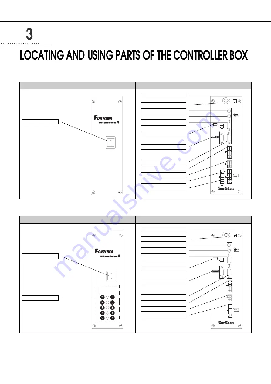
Control box back (Full Option Type)

Control box front (Full Option Type)

1) Front and back of control box

AC Power switch 

AC Power Input Power Cable

Control box grounding part

Option 2 Connector

Pedal Connector

Encoder Connector

Motor Power Connector

Position Detector Connector

P/U Connector

Option 1 Connector

A/B Button Connector

Solenoids Connector

Option 3

Button

A/B

Option1

Option3

S/M

Synchro

P/U

Motor

Encoder

Pedal

Option2

SUNSTAR ELECTRIC CO., LTD.

Control box back (Economic Type)

Control box front (Economic Type)

AC Power switch 

Simple Controller Board

AC Power Input Power Cable

Control box grounding part

Option 2 Connector

Pedal Connector

Encoder Connector

Motor Power Connector

Position Detector Connector

P/U Connector

Option 1 Connector

A/B Button Connector

Solenoids Connector

Button

A/B

Option1

S/M

Synchro

P/U

Motor

Encoder

Pedal

Option2

SUNSTAR ELECTRIC CO., LTD.

Summary of Contents for Fortuna IV Series

Page 1: ... with easiness please certainly read this manual before starting use 2 Keep this manual in safe place for reference when the machine breaks down S SU UN NS ST TA AR R M MA AC CH HIIN NE ER RY Y C CO O L LT TD D S SU UN NS ST TA AR R M MA AC CH HIIN NE ER RY Y C CO O L LT TD D ...

Page 2: ......

Page 3: ... functions high performance powerful operation enhanced durability and more sophisticated design to meet a number of user s needs 2 Please read this user s manual thoroughly before using the machine Make sure to properly use the machine to enjoy its full performance 3 The specifications of the machine are subject to change aimed to enhance product performance without prior notice 4 This product is...

Page 4: ...USER S MANUAL ...

Page 5: ...e of the sewing machine and motor 20 7 Things to be checked after installation 20 8 Program unit part names and method of use 21 9 Simple operation unit part names and method of use 41 10 Fortuna series 4 full function software method of use 46 11 Breakdown and troubleshooting 70 12 How to place for controller 71 13 Block diagram 72 Parts Book 73 C CO ON NT TE EN NT TS S ...

Page 6: ...t away from an hot object like a stove Keep the ambient humidity above 30 and below 95 Never use it near gases and explosives Do not use it at a spot located 1 000m or higer above sea level Keep the storage temperature higher than 25 degrees below zero and lower than 55 degrees Centigrade when not in use 3 Installation Follow the instruction carefully when installing it Be sure to start installing...

Page 7: ...parts including belts In case of remodelling or fitting of additional device be sure to follow safety standards and do not ever try to go ahead based on your own judgments Do not try to operate with the safety device removed Take care not to let water or coffee or something like those admitted into the Controller or the Motor Never drop the Controller or the Motor to the ground The instructions pr...

Page 8: ...ervomotor power plugs to the same power strip 6 Install the servomotor away from noise sources such as high frequency equipments and welding machines 7 Avoid electrical shock when servicing the controller box Wait for 6 minutes before opening the cover after turning off the power 8 When an error message Er sppears on the digital display take a note of the Er code and then turn on and off before re...

Page 9: ...that no dirt or a dirty substance may be piled up 10 When replacing the fuse use a standard item opening the cover as shown in the diagram 11 Make the length of the cable connected with an outside parts like stand up pedal as short as possible ...

Page 10: ...ids Connector Option 3 Button A B Option1 Option3 S M Synchro P U Motor Encoder Pedal Option2 SUNSTAR ELECTRIC CO LTD Control box back Economic Type Control box front Economic Type AC Power switch Simple Controller Board AC Power Input Power Cable Control box grounding part Option 2 Connector Pedal Connector Encoder Connector Motor Power Connector Position Detector Connector P U Connector Option 1...

Page 11: ...ication Hazardous voltage will cause injury Be sure to wait at least 360 seconds before opening this cover after turn off main switch and unplug power cord 고압 전류에 의해 감전될 수 있으므로 커버를 열 때 는 전원을 내리고 전원 플러그를 뽑고 나서 360초간 기다린 후 여십시오 WARNING 경 고 ...

Page 12: ... unit bracket Pedal unit bracket should be fixed to the area where the bar linked to the pedal that is to be attached to table leg becomes vertical The area where pedal unit bracket is attached depends on where the pedal is As in the figure attach control box to the lower right of the table with 15mm fixing screws Area where control box is to be attached The underside of the table front part Right...

Page 13: ...ogram unite without changing setting of synchronizer Setting needle bar up down stop with using optional program unite Turn on the down stop icon lamp by pressing needle bar up down stop button on the program unit to set needle bar down stop position When the up stop lamp on press needle bar up down stop button with pressing the button After that as in the figure letter showing information on the ...

Page 14: ... by pressing button without pressing button will not save reset values Setting needle bar up down stop position by using simple controller board front OP Turn on the up stop icon lamp by pressing needle bar up down stop button on the simple controller board to set needle bar up stop position When the up stop lamp turns on press E button while pressing needle bar up down stop button C Then as in th...

Page 15: ...f needle bar When the needle bar moves to the desired position save the position by pressing C key Then the screen automatically returns to the initial screen with a buzzer Caution Returning to the initial screen by pressing E button without pressing C button will not save reset values Caution The names of buttons on simple controller board are as follows A Button switch Switch for initial Reverse...

Page 16: ...he figure below attach program unit bracket to program unit with three fixing screws As in the figure attach the bracket with program unit to the head of machine firmly with two fixing screws 7 SunStar machine installed with program unit ...

Page 17: ...e phase 100V 120V 2 Single phase 200V 240V 3 Three phase 200V 240V Be sure to connect Protective Earth 2 Specification of electric current in wiring of power plug Be sure to use wiring materials which can stand electric current of higher than 15A ...

Page 18: ...ing solenoid supply voltage Basic setting values upon shipment J19 It is for a good operation of solenoid when AC input voltage changes Setting values of solenoid supply voltage against input voltage input voltage 220V series Solenoid with the rating current of 30V Solenoid with the rating current of 24V Input Voltage Setting Values Less than 210V J20 210V 230V J19 More than 230V J18 Input Voltage...

Page 19: ...e 110V Setting supplied voltage Solenoid with rating current of 30V Solenoid with rating current of 24V Input Voltage Setting Values Less than 100V J20 100V 120V J19 More than 120V J18 Input Voltage Setting Values Less than 90V J20 90V 100V J19 More than 100V J18 J22 J20 J19 J18 P5 P4 ...

Page 20: ...oltage for Solenoid Refer to How to change the electric voltage supplied for Solenoid 2 After the power is on Check whether the program unit is working Check the direction of rotation of the Sewing Machine In case the direction of rotation is not right action shall be taken to change set it right referring to the methods of changing the program and the list of changing functions N 65 in Group A Ch...

Reviews: