background image

1) FOR AT MOST USE WITH EASINESS,

PLEASE CERTAINLY READ THIS MANUAL

BEFORE STARTING USE.

2) KEEP THIS MANUAL IN SAFE PLACE 

FOR REFERENCE WHEN THE MACHINE 

BREAKS DOWN.

M

MM

ME

E--1

11

10

09

92

23

3

USER

S MANUAL

R

S

Su

un

nS

Sttaarr C

CO

O..,, L

LT

TD

D..

KM-1080 Series

Post Bed, 1-Needle 
Unison Feed Lock 
Stitch M/C

KM-1082 Series

Post Bed, 2-Needle 
Unison Feed Lock 
Stitch M/C

Summary of Contents for KM-1080 Series

Page 1: ...SE 2 KEEP THIS MANUAL IN SAFE PLACE FOR REFERENCE WHEN THE MACHINE BREAKS DOWN M MM ME E 1 11 10 09 92 23 3 USER S MANUAL R S Su un nS St ta ar r C CO O L LT TD D KM 1080 Series Post Bed 1 Needle Unison Feed Lock Stitch M C KM 1082 Series Post Bed 2 Needle Unison Feed Lock Stitch M C ...

Page 2: ......

Page 3: ...h performance powerful operation enhanced durability and more sophisticated design to meet a number of user s needs 2 Please read this user s manual thoroughly before using the machine Make sure to properly use the machine to enjoy its full performance 3 The specifications of the machine are subject to change aimed to enhance product performance without prior notice 4 This product is designed manu...

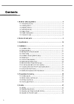
Page 4: ... 14 4 6 Supplying oil 19 4 7 Trial run Pedal operation 20 4 8 Machine Stop Position Check 20 4 9 Back tack button thread trimming type 21 4 10 Functional description of function switches 21 4 11 Adjusting Parameter of Sub Thread Adjusting Device 22 4 12 How to Use Dual Tension 22 4 13 Method for Adjustment of a Potentiometer 24 5 Preparations for sewing 25 5 1 Installing needle 25 5 2 Bobbin Inser...

Page 5: ...ng Device 35 8 3 Adjustment of Feed Dog Position 35 8 4 Height adjustment of feed dog 36 8 5 Adjustment of feed lift shaft cam and lower feed cam 36 8 6 Needle and Hook Timing 37 8 7 Clearance adjustment of hook and opener 38 8 8 Adjustment of Needle Plate Height 38 8 9 Adjustment of Presser Foot Height 38 8 10 Timing adjustment of the main auxiliary presser foot and needle 39 8 11 Trimmer 40 8 12...

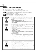
Page 6: ...he package and wrappings from the top Take special notice on the nails on the wooden boxes ⓑ Dust and moisture stains and rusts the machine Install an airconditioner and clean the machine regularly ⓒ Keep the machine out of the sun ⓓ Leave sufficient space of more than 50cm behind and on the right and left side of the machine for repairing ⓔ EXPLOSION HAZARDS Do not operate in explosive atmosphere...

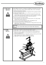
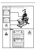
Page 7: ... as the control box ⓖ Stop the machine before threading the needle or checking after work ⓗ Do not step on the pedal when turning the power on ⓘ If possible install the machine away from source of strong electrical noise such as high frequency welding machines 1 4 Operating machine Warning Keep motor cover in place before operating turn off power before inspecting or adjusting 1 5 Safety devices W...

Page 8: ...se injury Be sure to wait at least 360 seconds before opening this cover after turn off main switch and unplug a power cord 고압 전류에 의해 감전될 수 있으므로 커버를 열 때는 전원을 내리고 전원 플러그를 뽑고 나 서 360초간 기다린 후 여십시오 CAUTION 주 의 Do not operate without finger guard and safety devices Before threading changing bobbin and needle cleaning etc switch off main switch 손가락 보호대와 안전장치 없이 작동하지 마 십시오 실 보빈 바늘교환시나 청소전에는 반드시 주전원의 스위치를...

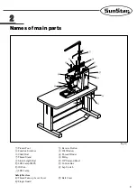
Page 9: ...e Button Function Switches Oil Window Climb Dial Thread Winder Thread Stand Pulley Stitch Length Dial OP Unit and Panel LED Lamp SMPS Control Box Oil Fan Lap Switch LED Lamp Safety Devices Thread Take up Lever Cover Belt Cover Finger Guard Fig 2 1 ...

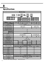
Page 10: ...o motor 750W Basic specifications Basic specifications Basic specifications Basic specifications Basic specifications Basic specifications Basic specifications Basic specifications Basic specifications Basic specifications Basic specifications Basic specifications Basic specifications Basic specifications 2 500 P 1 7mm 1 600 P 8 9mm 9 12 DP 35 19 23 134 35 Nm120 160 DP 35 22 25 134 35 Nm140 200 2 ...

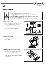
Page 11: ...e to press the lower part of the board leg of the machine or the whole body of machine falls backwards leading to physical injuries Fig 4 1 Fig 4 2 Fig 4 3 Only trained technicians should install and wire up the machine The machine weighs over 50 kg More than two persons should install the machine Do not plug in the machine until installation is completed If the operator mistakenly steps down on t...

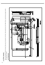
Page 12: ...able drawing Please use the table provided by Sunstar When using self made table the thick of table should be more than 40mm Please use table strong enough to sustain the weight of the machine 4 4 1 Slant table ...

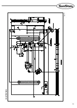
Page 13: ...13 4 4 2 Flat table Fig 4 4 ...

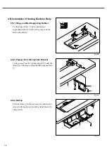
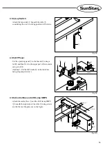
Page 14: ... at the grooves on the table using nails 4 5 2 Presser Foot Lift Cylinder Bracket Fix the presser foot lift cylinder bracket under the table as in the figure using the M8 hexagonal bolt 4 5 3 Oil Fan Find the oil fan in the accessory box and attach it aligned with the presser foot lift cylinder bracket using screws Fig 4 5 Fig 4 6 Fig 4 7 ...

Page 15: ...et using a bolt and then fix it to the upper part of the rear arm using a bolt Optional Fix the OP bracket to the table face using a tapping screw 4 5 6 Control Box and LED Lamp SMPS Attach the control box and the LED lamp SMPS beneath the right side of the table using screws and fix them at the places as in the figure Fig 4 8 Fig 4 9 Fig 4 10 Option 20mm 21 5mm ...

Page 16: ...st the tension of the belt to make the belt pressed 10mm when the center is pressed by a finger as in the figure and tightly fasten the fixing nut 4 5 8 Sewing Machine Body 1 Place the two hinges on the rear bed of the sewing machine and tightly fasten them using the screw 2 Settle the hinge on the hinge rubber of the table and place the sewing machine body on the bed base rubber 3 Insert the mach...

Page 17: ...gualtor is no highr than 0 3Mpa 4 5 12 Description of label symbols Label Sign Cylinder Function S1 S2 S3 S4 S5 S6 S7 S8 Backtack Trimming Hem height difference Stitch length conversion Thread release Main Thread release Sub Presser foot Seam guide Add the initial and last backtack sewing function and perform reverse sewing Perform trimming When the cylinder is in motion sewing is performed using ...

Page 18: ...ly Secure the thread spool stand assembly onto the table using washer and nut on the right side Fig 4 16 4 5 13 Pnematic wiring diagram by model KM 1080BL KM 1082BL KM 1082BLH KM 1082BL 7 Option Button switch cable KM 1080BL 7 KM 1080BLH ...

Page 19: ...f 1 500 spm per minute for the first four to five days of operation and use the machine at the normal speed afterwards Then it is able to keep the machine at the best conditions 4 6 Supplying oil High Low Fig 4 17 Fig 4 19 Fig 4 18 Fig 4 20 Operate the machine only after supplying oil when the machine is used for the first time or has been left unused for a long time Only use genuine lubricant of ...

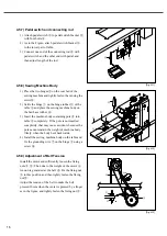
Page 20: ...tion of to D and then replacing pedal to the position of A needle will stop higher than the upper surface of needle plate after trimming 4 8 1 Check for up stop position of needle bar The needle bar is at the highest stop position when the thread take up lever stops at the highest position If their positions are not proper adjust the magnetic holder embedded at the N U punched mark of the pulley l...

Page 21: ... backtack sewing function 3 Presser bar overlapping change switch When pressing the switch the lamp is on Then regardless of the set value at the top cover dial the overlapping portion of presser bar becomes 7mm at maximum When pressing it again the lamp is off and the set value at the top cover dial is applied 4 Supplementary thread tension switch When the switch is not pressed the tread tension ...

Page 22: ...ad adjusting device enables users to easily increase the tension of the upper thread according to the sewing material height difference and conditions For two needle model if a dual tension individual operating type optional is used the left and right tension of the upper thread can be independently adjusted while sewing materials with height difference on the left and right sides The sub thread a...

Page 23: ...wing 4 2 Optional Specifications When sewing the materials with different height on left and right sides the independently operating optional dual tension can be used to get the best sewing quality As in Figure 4 26 when sewing the materials with different height on left and right sides upper thread tension should be given differently to the left and right sides to get the best sewing quality As s...

Page 24: ...y area remains fixed Details Screen display How to operate Turn on the power Press button then press button while holding down button to change screen No 1 2 3 4 5 11 Set the the adjustment dial for mutual overlapping portion of presser foot to 3 mm and press the key then the screen is automatically changed with the buzzer sound Set the the adjustment dial for mutual overlapping portion of presser...

Page 25: ... the flap holding the bobbin Remove the bobbin from the bobbin case using tweezers 5 2 2 Bobbin Insertion Take out the lower thread from the bobbin through the thread passage and below the tension spring plate and make the loose lower thread length 50mm Bobbin can be inserted in the reverse order of the bobbin removal 50mm Fig 5 1 Fig 5 2 Make sure to turn off the power switch when removing the bo...

Page 26: ...ding loosen screw and adjust bobbin winder adjusting plate 5 4 Inserting upper thread 1 Place the thread take up at its the highest position by turning pulley before inserting the upper thread 2 The adequate length of upper thread extending from the needle hole is 50mm Fig 5 3 Fig 5 4 80 Always turn off the power when inserting upper thread If the pedal is accidentally stepped the machine might un...

Page 27: ...h the plug in the machine will start automatically and can cause severe injuries When inserting upper thread When replacing bobbin or needle When the machine not in use or the operator leaving the work place Caution Sewing Type Cause Troubleshooting Good sewing in balance Upper thread tension is too weak Lower thread tension is too strong Upper thread tension is too strong Lower thread tension is ...

Page 28: ...unter clockwise the tension weakens Fig 6 3 6 2 3 Main thread adjusting device 1 The tension of the main thread adjusting devices should be set at the minimum as possible 2 Loops should be created at the center of the sewing material Make sure that thread break does not occur on the ultra light material due to strong thread tension 3 Adjust the main thread adjusting devices to create stitches at r...

Page 29: ...n in a prompt manner 2 The tension of the supplementary thread adjusting devices should be set lower than that of the main thread adjusting devices The tension can be turned on off with the functional switch 3 The tension of the supplementary thread adjusting device gets stronger when it is turned clockwise It gets weaker when the device is turned counter clockwise Fig 6 5 6 2 5 Operation of threa...

Page 30: ...everse lever descends and stitch count decreases 6 5 Adjustment of Presser Foot Lift The overlap between the main presser foot and the sub presser foot could be set at 1 7mm using the climb dials which adjust the presser foot lift Place the desired numbers of the climb dials at the punched mark and the main presser foot and the sub presser foot overlap according to the set value For the sewing sec...

Page 31: ...at the sewing fabric is slipped away 2 Turn the pressure adjusting dial to adjust the presser foot pressure 3 When the dial is turned clockwise the pressure gets stronger Otherwise the pressure gets weaker Stitch Type Cause Solution Balanced good stitch Stitch skipped inconsistent stitch length Puckering Increase pressure Decrease pressure Fig 6 10 ...

Page 32: ...ith soap when they are smeared with lubricant If lubricant is in the eye instantly wash it with running water and see a doctor Never drink lubricants since they can cause vomiting or diarrhea Go to see a doctor if you mistakenly drink lubricant Keep the oil out of the reach of children Keep the oil away from heat Use both hands when bending the machine backwards or returning it to the original pos...

Page 33: ...ure that lubricant does not overflow Fig 7 2 High Low 7 1 3 Checking 1 When needle is deformed or the end of needle is damaged change the needle 2 Check if upper thread is inserted correctly Refer to 5 4 Inserting upper thread 3 Run trial sewing Fig 7 3 1 Make sure that lubricant does not go over the HIGH mark This may cause the leakage of lubricant Tightly fasten the screw at the oil thank outlet...

Page 34: ... clockwise Then the thread take up spring s operation timing gets faster Otherwise the operation timing gets slower Fig 8 3 The operation timing of the thread take up lever spring is standard when the stopper screw is at the center of the guide plate Fig 8 1 Fig 8 2 Fig 8 3 For machine maintenance and repair consult with qualified technicians For electrical maintenance and repair consult with qual...

Page 35: ...f the feed rock shaft crank is moving 3 If the feed rock shaft crank is moving loosen the fixing screw for the changer connection crank and use the changer angle adjusting hole to adjust the changer s angle 4 If the feed rock shaft crank is not moving when the upper shaft pulley is turned completely fasten all fixing screws 8 3 2 Feed Dog Position on Needle Plate When the stitch length is maximum ...

Page 36: ...to be 1 2mm 5 When adjustment is completed tightly fasten the fixing screw 8 5 Adjustment of feed lift shaft cam and lower feed cam 1 Set the stitch count at maximum and pull down the needle bar at the lowest point 2 Make the second fixing screw of the feed lift shaft cam move vertically and tighten the fixing screw 3 Lower the needle bar to the lowest point 4 Move the first fixing screw of the lo...

Page 37: ...k edge at the center of the needle and tightly fasten the fixing screw for the lower shaft collar 8 6 2 Clearance adjustment between needle and hook 1 Loosen the needle plate base fixing screw and then the hook base fixing screws Adjust the hook base in the arrow direction and set the distance between the needle and the hook edge to be 0 1mm 2 Tightly fasten the hook base fixing screws after adjus...

Page 38: ...e base adjusting cam to adjust the needle plate height 3 When adjustment is completed tightly fasten the fixing screw for the needle plate base adjusting cam the needle plate base adjusting screw and the needle plate base fixing screw 0 8mm Fig 8 12 Fig 8 13 0 5 0 7mm 8 9 Adjustment of Presser Foot Height 1 To ensure presser foot s smooth vertical movement release the presser foot presser adjustin...

Page 39: ... Loosen the clamp screw and turn the machine until the needle tip and the upper part of the feed dog come to meet on the surface of the needle plate 4 As in 2 above make the main and subordinate presser feet contact the needle plate at the same time and after that tightly fasten the tightening screw to finish the adjustment 5 After adjustment place back the rubber cap on the upper lid Fig 8 16 8 1...

Page 40: ...ten the fixing screw for the moving blade shaft crank Fig 8 18 8 11 2 Fixed blade and Lower Thread Holder The moving blade contacts the fixed blade at the 1 3 point of its length to conduct trimming as safe as possible with the minimum pressure When trimming is made the lower thread holder contacts the moving blade securely holding the lower thread Adjustment can be made in the following order 1 I...

Page 41: ...ews 2 Adjust the trimmer cylinder piston to place the roller 1mm away from the lowest point of the trimmer cam Then fasten the fixing screws 3 Unfasten the trimmer cam fixing screws 4 Adjust the trimmer cam with the needle bar at the lowest point Arrange in a straight line and fasten the trimmer cam fixing screws 1mm Fig 8 20 8 12 Safety Clutch The safety device for the lower shaft timing pulley i...

Page 42: ...ition Bent needle or broken needle tip Thread passing at wrong position Wrong timing of needle and hook Wrong timing of needle and hook Wrong timing of needle and hook Remaining length of upper thread is short Due to bobbin racing during trimming lower thread dropping from bobbin case becomes too short to go up Unable to lift lower thread due to weak take up lever spring Reinsert the needle correc...

Page 43: ...roove of movable and fixed blades Wrong needle insertion Insufficient crossing quantity of movable and fixed blade Too strong upper thread tension Too thick a needle for thread Take up lever pulls out the upper thread because the needle up and down position is too high Reduce tension of upper thread Increase tension of lower thread Increase upper thread tension Decrease tension of lower thread Adj...

Reviews: