
31
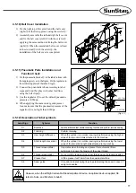
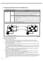
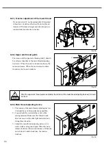
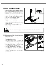
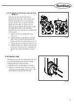
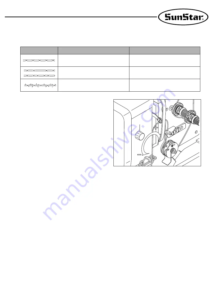
6.6) Adjustment of Presser Foot Pressure
6.6.1) Presser Foot Pressure
1) Adjust the presser foot pressure to remain weak if
possible (to the extent that the sewing fabric is
slipped away)
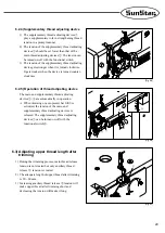
2) Turn the pressure adjusting dial
①
to adjust the
presser foot pressure.
3) When the dial is turned clockwise, the pressure
gets stronger. Otherwise, the pressure gets
weaker.
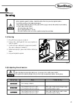
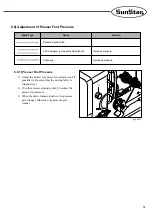
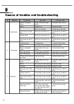
Stitch Type
Cause
Solution
Balanced good stitch
Stitch skipped, inconsistent stitch length
Puckering
Increase pressure
Decrease pressure
[Fig. 6-10]
①
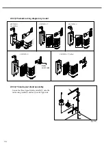
Summary of Contents for KM-1080 Series
Page 2: ......
Page 13: ...13 4 4 2 Flat table Fig 4 4 ...