39
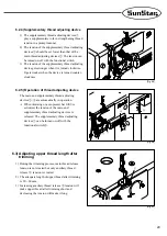
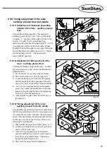
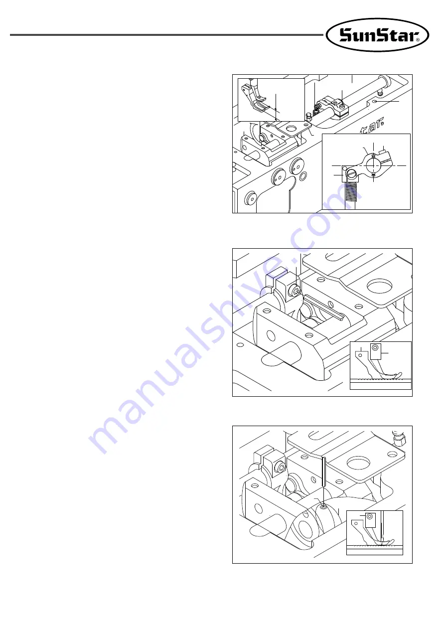
[Fig. 8-15]
8.10) Timing adjustment of the main
·
auxiliary presser foot and needle
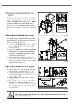
8.10.1) Adjustment of maximum ascending
amount of the main
·
auxiliary presser
foot
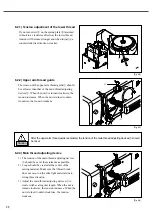
The maximum lifting quantity of the main and
auxiliary presser foot is 7 mm. First, set the upper
lid dial at
“
1
”
and take out the upper lid. Move the
body
①
of a climb device towards the arrow
direction until it reaches the stopper plate
②
. (At this
time, make the surface of the climb shaft cylinder
knuckle
⑤
contact the upper cross section of the arm
⑥
and then fasten the tightening screw
③.
) Tighten
the crank clamp screw
⑥
. After adjustment,
reassemble the upper lid.
8.10.2) Adjustment of lifting amount of the
main
·
auxiliary presser foot
The height of lifting amount of the main
·
auxiliary
presser foot must be equal. Make the adjustment as
indicated below.
1) Set the presser foot overlap at the maximum.
2) Take out the rubber cap from the upper lid.
3) Loosen the clamp screw
①
and turn the machine
until the needle tip and the upper part of the feed
dog come to meet on the surface of the needle plate.
4) As in 2 above, make the main and subordinate
presser feet contact the needle plate at the same
time and after that, tightly fasten the tightening
screw
①
to finish the adjustment.
5) After adjustment, place back the rubber cap on
the upper lid.
[Fig. 8-16]
8.10.3) Timing adjustment of the main
·
auxiliary presser foot and needle
As a standard, the needle tip enters the needle hole of
the feed dog immediately after the main presser foot
①
touches the feed dog. Likewise, the main presser
foot
①
comes apart from the feed dog right after the
needle tip comes out of the feed dog. Refer to the
following for adjustments.
1) Disassemble the upper lid with the dial set at
“
1
”
.
2) Loosen two fixing screws of vertical movement
cam
②
of the presser foot.
3) After securing the needle bar in the highest
position, hold the No.1 screw
③
of the cam
②
so
that it faces up perpendicularly. Afterwards,
tighten the cam-fixing screws.
4) Place back the upper lid after adjustment.
[Fig. 8-17]
③
②
①
④
①
③
③
⑤
⑥
②
7mm
①
Summary of Contents for KM-1080 Series
Page 2: ......
Page 13: ...13 4 4 2 Flat table Fig 4 4 ...

