41
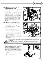
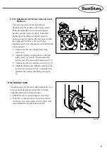
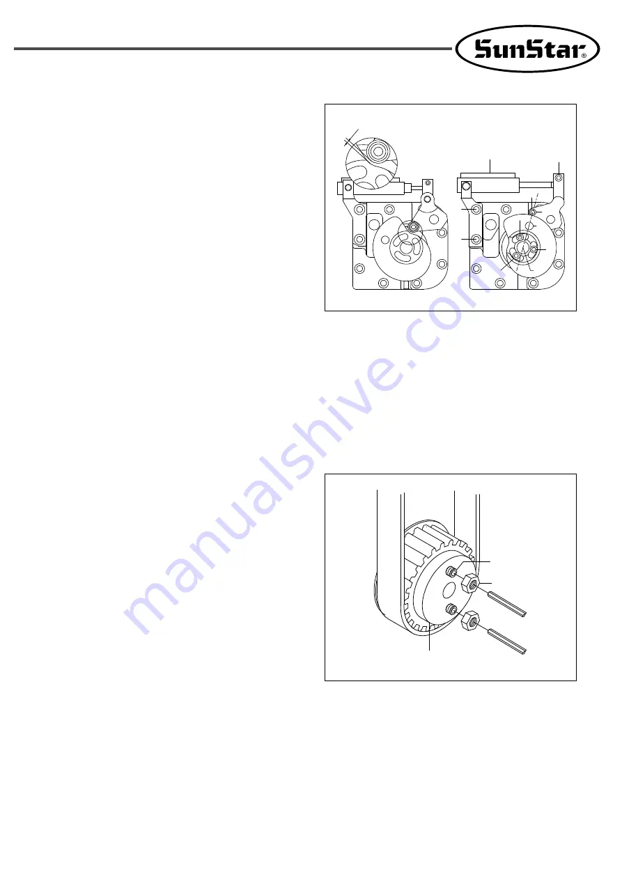
8.11.3) Adjustment of Trimmer Cam and Lever
Positions
The rotary movement of the fixed blade is
determined by the position of the trimmer cam
⑨
.
When the thread take-up lever is at the highest
position, the trimmer lever roller
⑧
touches the
highest tip of the trimmer cam
⑨
,
⑩
. However,
during sewing, the roller and the cam do not contact
each other and the distance between them is
maintained at 0.1mm. Adjustment can be made in the
following order:
1) Unfasten the trimmer cylinder block fixing
screws
①
,
②
.
2) Adjust the trimmer cylinder piston to place the
roller 1mm away from the lowest point of the
trimmer cam. Then fasten the fixing screws
①
,
②
.
3) Unfasten the trimmer cam fixing screws
③
,
④
,
⑤
.
4) Adjust the trimmer cam with the needle bar at the
lowest point. Arrange
⑥
,
⑦
,
⑧
in a straight line
and fasten the trimmer cam fixing screws
③
,
④
,
⑤
.
③
③
②
④
④
⑤
⑦
⑧
⑤
⑥
1mm
①
[Fig. 8-20]
8.12) Safety Clutch
The safety device for the lower shaft timing pulley
②
is
to prevent hook damage caused by thread winding
around the hook or the setting disruption.
1) Slightly loosen two piston stopper screw nuts
③
.
2) When the two piston stopper screws
①
are turned
clockwise, it increases torque, and vice versa. After
torque adjustment, tightly fasten the nut
③
.
[Fig. 8-21]
③
②
①
Summary of Contents for KM-1080 Series
Page 2: ......
Page 13: ...13 4 4 2 Flat table Fig 4 4 ...

