background image

Best Quality

Best Price

Best Service

SunStar CO., LTD.

R

1. Thank you for purchasing our product. Based on the rich expertise and

experience accumulated in industrial sewing machine production, SUNSTAR

will manufacture industrial sewing machines, which deliver more diverse

functions, high performance, powerful operation, enhanced durability, and

more sophisticated design to meet a number of user’s needs. 

2. Please read this user’s manual thoroughly before using the machine. Make

sure to properly use the machine to enjoy its full performance. 

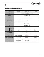
3. The specifications of the machine are subject to change, aimed to enhance

product performance, without prior notice. 

4. This product is designed, manufactured, and sold as an industrial sewing

machine. It should not be used for other than industrial purpose.  

Summary of Contents for KM-360J SERIES

Page 1: ...USER S MANUAL KM 360J SERIES R High Speed 1 Needle Needle Feed Bottom Hemming Sewing Machine Mechanical Part ...

Page 2: ...e powerful operation enhanced durability and more sophisticated design to meet a number of user s needs 2 Please read this user s manual thoroughly before using the machine Make sure to properly use the machine to enjoy its full performance 3 The specifications of the machine are subject to change aimed to enhance product performance without prior notice 4 This product is designed manufactured and...

Page 3: ...ine Type J General Attached with near jean accessories MODEL KM 360 J 7 Manual trimming Automatic trimming E M Mechanical puller needle bar oscillating system Electronic puller needle bar oscillating system ...

Page 4: ...11 4 3 Machine Placement on the Table 12 4 4 Part Assembly 13 5 Preparation Before Use 15 5 1 Oil Supply 15 5 2 Needle Installation 15 5 3 Lower Thread Placement 15 5 4 Bobbin Case Insertion and Disposal 16 5 5 Lower Thread Winding 16 5 6 Upper Thread Tension Adjustment 17 5 7 Remaining Thread Adjustment After Trimming 18 5 8 Upper Thread Placement 18 5 9 Pressured Air Input and Air Pressure Adjus...

Page 5: ... Stitch Length Adjustment 22 6 9 Pneumatic Wiper Adjustment 23 6 10 Trimmer Cam Adjustment 23 6 11 Blade Position Adjustment 23 6 12 Thread Take up Lever Adjustment 24 7 Causes of troubles and troubleshooting 25 8 Table Drawings 27 8 1 KM 360J 7M Type A 27 8 2 KM 360J 7M Type B 28 8 3 KM 360J 7M Type C 29 9 Pneumatic Circuit Diagram 30 9 1 KM 360J 7M E 30 ...

Page 6: ...ins and rusts the machine Install an airconditioner and clean the machine regularly ⓒ Keep the machine out of the sun ⓓ Leave sufficient space of more than 50cm behind and on the right and left side of the machine for repairing ⓔ EXPLOSION HAZARDS Do not operate in explosive atmospheres To avoid explosion do not operate this machine in an explosive atomsphere including a place where large quantiti...

Page 7: ...threading the needle or checking after work ⓗ Do not step on the pedal when turning the power on ⓘ If possible install the machine away from source of strong electrical noise such as high frequency welding machines 1 4 Operating machine Warning Caution Warning Keep motor cover in place before operating turn off power before inspecting or adjusting 1 5 Safety devices ⓐ Safety label It describes cau...

Page 8: ...경 고 Hazardous voltage will cause injury Be sure to wait at least 360 seconds before opening this cover after turn off main switch and unplug a power cord 고압 전류에 의해 감전될 수 있으므로 커버 를 열 때는 전원을 내리고 전원 플러그를 뽑 고 나서 360초간 기다린 후 여십시오 Caution 1 2 1 7 Contents of marks Warning Caution mark is attached on the machine for safety When you operate the machine follow the directions on the mark 1 6 Caution mark po...

Page 9: ...eumatic Manual Driven by the stepping pulse motor Driven by the stepping pulse motor 500W direct drive AC servo motor 500W direct drive AC servo motor Clutch motor Mechanical Mechanical Mechanical Mechanical 2 4 2mm Presser Foot Lift Use Lubrication Sewing Speed Stitch Length Needle Bar Stroke Thread Take up Lever Stroke Needle Hook Pants Hem Size Automatic Trimmer Wiper Device Puller Driving Syst...

Page 10: ...ifter Pneumatic auto presser bar lifter Presser foot Control box Lap switch Power switch Oil window Hammer Pneumatic auto presser foot lifter Sewing machine pulley Program unit Thread stand Safety Gears Thread Take up Cover Finger Guard Motor Cover Gear Cover left Gear Cover right ...

Page 11: ...ent power supply from a strong magnetic field and high frequency product and keep the sewing machine away from them C Use a safe low voltage when auxiliary devices and accessories are attached to the control box D Take caution not to spill water or coffee into the control box or the motor E Do not drop the control box and the motor Sewing machine must be installed by properly trained engineers Con...

Page 12: ...using the bed hinge support assembly part F Completely fasten the fixing bolt for the bed hinge bracket and tightly fasten the bed hinge bracket to the table 12 4 3 Machine Placement on the Table A Fix the control box to the table B Put the oil fan on the marked place and fix the bed hinge bracket to the holes Fig 1 Fig 2 Fig 3 Loosely fasten the bed hinge bracket fixing bolts and tightly fasten t...

Page 13: ...t KM 360 M 4 4 Part Assembly A Attach the motor cover to the rear side of the machine using the fixing screw However in case of manual trimming type attach the belt cover A B to the rear side of the machine using the fixing screw B Assemble the operating panel to the bracket and attach them to the rear side of the machine KM 360J 7M KM 360J 7E KM 360J 7M KM 360J M Fig 4 Fig 5 Fig 6 Fig 7 ...

Page 14: ...eath the table and fix it with a nail KM 360J 7E M F Fix the manifolder bracket beneath the table and fix it using a screw KM 360J 7E M Fig 8 Fig 9 Fig 10 Make sure the head supporting stick completely inserted into the table Otherwise when the sewing machine head is pushed backward it is not stable and dangerous Caution ...

Page 15: ...nd fully insert the needle into the hole as in the figure And fix the needle with a fixing screw 5 3 Lower Thread Placement A Insert the bobbin into the bobbin case as in the figure B Pass the lower thread through the slot of the bobbin case and the lower part of the tension spring User s work direction Needle direction Fig 11 Fig 12 Fig 13 The power switch must be turned off for needle installati...

Page 16: ... with the presser bar lifter F When the pedal is stepped the sewing machine starts operating and the thread is wound around the bobbin G When thread winding is complete the thread winder lever is automatically returned H Separate the bobbin and cut the thread with the thread winder blade Loosen the adjusting screw and adjust the thread winder adjusting plate to adjust the thread volume on the bobb...

Page 17: ... the lower thread tension by adjusting the tension adjusting screw to the extent that the bobbin case slowly drops due to its own weight when the thread tip is held as in the figure 5 6 2 Upper Thread Tension A Adjust the lower thread tension and then the upper thread tension to produce evenly created good stitches B Pull down the presser bar C Turn the tension adjusting nut of the main thread adj...

Page 18: ...the sewing machine to locate the thread take up lever at the highest position and pass the thread through the thread take up lever This makes threading easier and prevents thread escape when sewing starts B Make the remaining thread as long as 35 40mm from the needle eye 5 9 Pressured Air Input and Air Pressure Adjustment KM 360J 7E M A Connect the quick joint plug attached to the table to the qui...

Page 19: ... and turn it clockwise as in the figure This increases pressure If it is turned counter clockwise pressure decreases Adjust the pressure to the appropriate level of 0 49 0 54MPa 5 5 5Kgf cm2 as marked on the pressure gauge and then return and settle the adjusting handle Fig 21 ...

Page 20: ...of the oil rejecter cover Make sure to set the distance between the needle eye and the tip of the hook at 0 0 5mm B Loosen the three screws and set the tip of the hook in line with the center of the needle Adjust the distance between the tip of the hook and the needle at 0 05 0 1mm C Tightly fasten the three screws 6 3 Adjustment of Thread Take up Lever Lubrication As in the figure when the mark o...

Page 21: ...fabric B Lubrication Volume Adjustment Turn the lubrication volume adjusting screw on the lower shaft front bushing clockwise direction and then lubrication volume increases If it is turned counter clockwise direction lubrication volume decreases Hook Lubrication test sheet Oil strip Oil strip Max limit Decrease Increase Weaker Stronger Stronger Weaker Min limit 6 5 Puller upper Pressure Adjustmen...

Page 22: ...ove the puller gear cover right B Set the desired stitch length using the stitch length table and make a new conversion gear ready C Loosen the tightening screw and remove the present conversion gear D Replace it with a new conversion gear and fasten the tightening screw E After the conversion gear replacement adjust the needle feed volume F Press the feed adjustment button on the arm face G Turn ...

Page 23: ...o the trimmer cam C Turn the pulley to make the needle bar s carved line meet the bottom of the oil reject cover Then adjust the trimmer cam to make the trimmer main lever move to the left D Loose the trimmer cam tightening screw for adjustment When adjustment is complete tightly fasten the screw 6 11 Blade Position Adjustment A Remove the rubber cap B Turn the pulley to place the thread take up l...

Page 24: ...24 6 12 Thread Take up Lever Adjustment A Loosen the nut B Turn the adjusting screw to set the distance between the thread release lever roller and the trimmer cam at 0 5mm C Fasten the nut Fig 33 ...

Page 25: ...ition Bent needle or broken needle tip Thread passing at wrong position Wrong timing of needle and hook Wrong timing of needle and hook Wrong timing of needle and hook Remaining length of upper thread is short Due to bobbin racing during trimming lower thread dropping from bobbin case becomes too short to go up Unable to lift lower thread due to weak take up lever spring Reinsert the needle correc...

Page 26: ...roove of movable and fixed blades Wrong needle insertion Insufficient crossing quantity of movable and fixed blade Too strong upper thread tension Too thick a needle for thread Take up lever pulls out the upper thread because the needle up and down position is too high Reduce tension of upper thread Increase tension of lower thread Increase upper thread tension Decrease tension of lower thread Adj...

Page 27: ...27 8 8 Table Drawings 8 1 KM 360J 7M Type A ...

Page 28: ...28 8 2 KM 360J 7M Type B ...

Page 29: ...29 8 3 KM 360J 7M Type C ...

Page 30: ...30 9 9 Pneumatic Circuit Diagram 9 1 KM 360J 7M E ...

Reviews: