


20
66
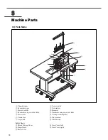
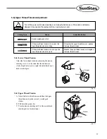
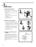
Maintenance
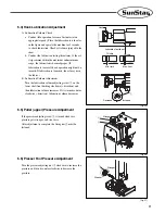
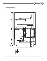
6.1) Needle Bar Height Adjustment
When the needle bar
①
is at the lowest position, set the
carved line
ⓐ
of the needle bar
①
to meet the bottom of the
oil rejecter cover
②
.
A. Turn the pulley and place the needle bar
①
at the lowest
position.
B. Remove the rubber cap
③
.
C. Slightly loosen the screw
④
and adjust the position of
the needle bar
①
.
D. Completely fasten the screw
④
.
E. Place back the rubber cap
③
.
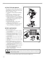
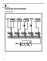
6.2) Needle, Hook Timing Adjustment
A. Turn the pulley and lift the needle bar from the lowest
position. As in the figure, set the carved line
ⓐ
in line
with the bottom of the oil rejecter cover
②
. Make sure to
set the distance between the needle eye and the tip of the
hook at 0~0.5mm.
B. Loosen the three screws
⑤
and set the tip of the hook
③
in line with the center of the needle
④
. Adjust the
distance between the tip of the hook
③
and the needle
④
at 0.05~0.1mm.
C. Tightly fasten the three screws
⑤
.
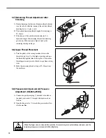
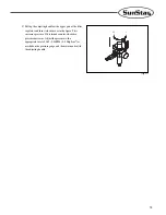
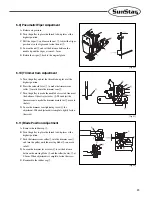
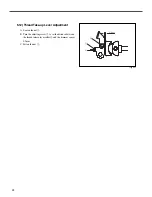
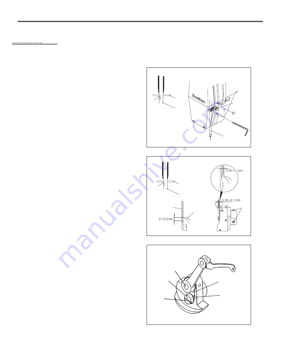
6.3) Adjustment of Thread Take-up Lever
Lubrication
As in the figure, when the mark
②
on the lubrication
adjusting pin
①
head is in line with the center of the thread
take-up lever crank shaft hole
③
, lubrication volume is
maximum. When the pin is turned left or right and the mark
is adjusted toward the edge
⑤
of the link cam washer
④
,
lubrication volume gets smaller.
If the edge of the link cam washer is passed, no lubricant is
supplied.
①
①
①
④
③
⑤
④
⑤
③
②
①
②
ⓐ
④
②
③
ⓐ
[Fig. 22]
[Fig. 23]
[Fig. 24]


