


12
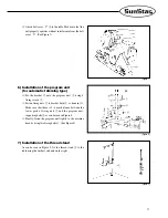
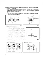
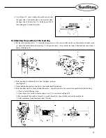
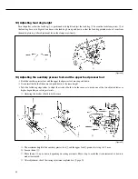
8) Assembly of the location detector and its control method (for automatic trimming type)
⑴
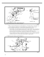
Installation of the location detector
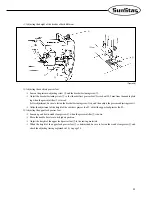
Assemble in the order of marked numbers as can be seen in Figure 10. Then, following Figure 11, make adjustments to
place the photo film at the center of the sensor housing
①
, by moving the shaft
②
to the right and left. Then, tighten the 2
fixing screws
③
by using the hexagonal wrench
④
.
[Note]
As can be seen on Figure 10, make sure that the marks
“
DOWN
”
and
“
UP
”
face the front when looking from the pulley side.
Film adjustment is completed upon shipment.
[Figure 10]
[Figure 11]
③
①
②
⑤
④
⑥
⑦
⑧
①
Photo film
(horizontal adjustment)
③
④
②
⑦
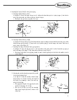
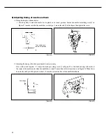
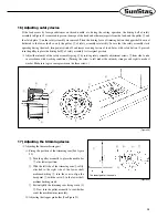
⑵
Film adjustment of location detector
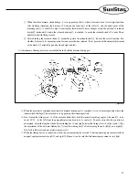
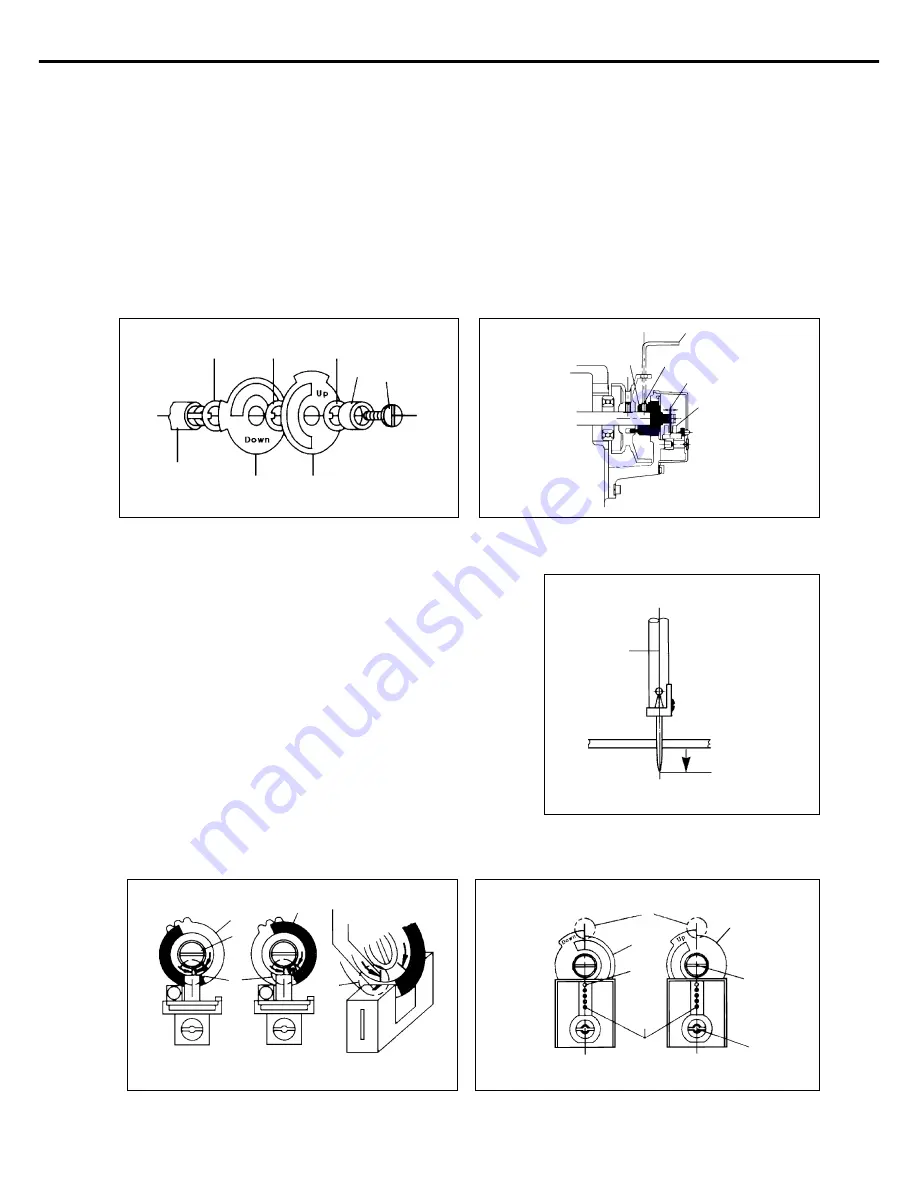
For new model type (see Figures 12, 13)
Manually turn the pulley so that the needle bar is placed where it
starts rising from the lowest point. Unfasten the film-fixing screw
①
in Figure 13, and for
“
DOWN
”
film A, align the film
adjustment base line with the sensor adjustment base line, as can
be seen in
ⓚ
. Then, using the fixing screw
①
, fasten the film
only as tightly as to prevent it from turning. In the same way,
place the thread-take-up lever at its highest point. Once again
unfasten the fixed screw
①
, and align the
“
UP
”
film B like
ⓚ
.
Now, be careful not to move the previously set
“
DOWN
”
film A.
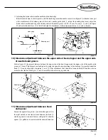
For old model type (See Figure 14)
Adjust in the same way as for new model to make the right side
ⓚ
of the film
’
s projecting part aligned to the center of the sensor
base line.
[Figure 13]
[Figure 14]
DOWN Film
Adjustment
UP Film
Adjustment
[New model location detector]
[Old model location detector]
ⓚ
B
①
A
sensor
sensor
base line
Sensor adjustment base line
Film adjustment base line
DOWN Film
Adjustment
UP Film
Adjustment
A
①
ⓚ
B
ⓚ
Photo sensor
Fixing screw
Lowest position
of needle bar
[Figure 12]
Summary of Contents for KM-560
Page 34: ...34 5 Table Drawing ...


