

25
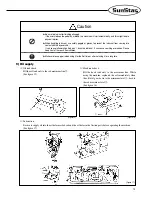
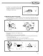
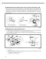
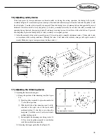
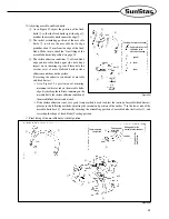
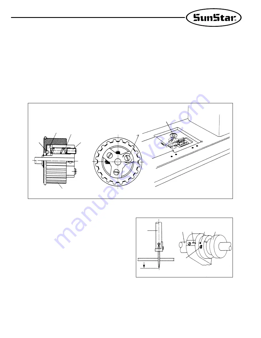
16) Adjusting safety device
If the load occurs by foreign substances on thread, needle, etc, during the sewing operation, the driving ball of safety
assembly in Figure 49 is removed to prevent damage of the hook and other major parts from the lood, and the pulley
②
and
the clutch plate
③
on the safety assembly are removed. Then, the driving force of timming belt on the upper shaft does not
delivered to the lower shaft, so only the pulley
②
of safety assembly rotates idly. In case that the safety assembly starts
operating during the work, turn power switch off and remove causing factors of load. Later, with safety button
④
pressed,
turn the pulley to place the driving ball
①
of safety assembly to its original position.
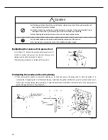
※
Adjust the intensity of the safety assembly spring
⑥
by rotating safety assembly adjustment screws
⑦
from side to side
in accordance with working conditions. (Turning the screw to left makes the intensity stronger, and right to make it
weaker. Make sure to give same pressure on the three screws.)
[Figure 49]
①
③
⑥
⑦
②
⑦
④
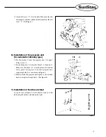
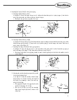
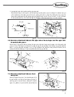
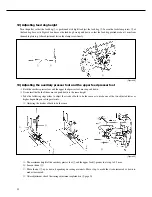
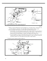
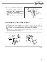
17) Adjusting the trimming device
⑴
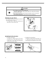
Adjusting the trimmer driving part
Fixing the position of the trimming cam (See figure
50)
①
Turn the pulley manually to place the needle bar
⑦
at its lowest position.
②
With the left side of the trimming cam
①
softly
attached to the right side of the lower shaft
medium bushing
②
, turn the cam to align the
base point
③
with the carve
④
in the lower shaft
medium bushing crank.
③
Fasten tightly the trimming cam fixing crews (3)
⑤
. Now, turn the pulley manually to see whether
or not the machine turns smoothly.
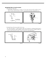
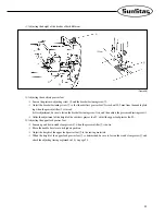
Adjusting the stopper pin holder (See Figure 51)
[Figure 50]
①
③
④
②
⑤
⑦
The lowest point of the needle
Summary of Contents for KM-560
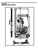
Page 34: ...34 5 Table Drawing ...


