


27
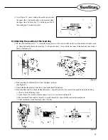
①
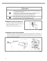
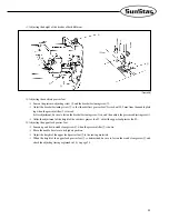
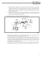
When the whole trimmer shake linkage
①
is in up position, that is, when it has come back to its original position
after finishing trimming, the distance
④
between the lower part of the roller
②
and the equal point of the
trimming cam
③
is about 0.8~1mm. Assuming that this distance
④
never changes, adjust the position of solenoid
bracket
⑦
horizontally, where the solenoid housing
⑥
is attached, to make the solenoid stroke
⑤
4 mm. Then,
tightly fasten with fixing screw
⑧
.
②
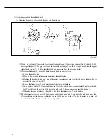
After adjusting the solenoid stroke
⑤
, manually operate the solenoid shaft
⑨
towards the arrow direction. See
whether it returns to its original position fast and smooth when released. If not, proceed with horizontal adjustment
of the bracket
⑦
minutely up and down and right and left.
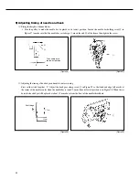
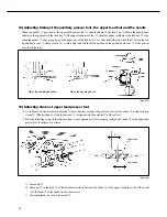
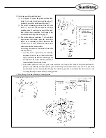
⑵
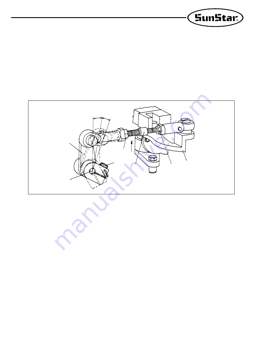
Adjustment of linking device for movable knife shaft and the trimmer driving part
When the previously explained adjustment of trimmer driving part is complete, it is in its normal position where the
trimmer shake linkage
①
has returned to its up position after trimming action.
First, loosen the fixing screw
②
of the movable knife shaft, hold the initial assembling angle of the crank
③
to be
about 15
°
30
′
to the left from the perpendicular line drawn to its center
④
. To make sure that this position is
maintained, adjust the length of the ball joint linking bar
⑤
, and tightly fasten the fixing screw
②
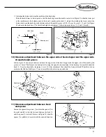
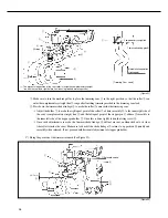
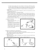
of the crank. (
※
For
the adjustment of the ball joint linking bar
⑤
, turn the linking bar
⑥
after loosening the nuts (left)
⑥
and (right)
⑦
.
Nut (left) is left screw and nut (right) is right screw.)
When the linking device is connected as such, the movement angles of crank
③
during trimming movement results in
an equal angle movements for left
⑧
and right
⑨
. Hence, it can be said that the trimming movement is very light.
[Figure 53]
③
④
②
⑥
⑤
⑦
①
⑧
⑨
15。30´
Summary of Contents for KM-560
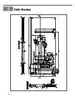
Page 34: ...34 5 Table Drawing ...


