14
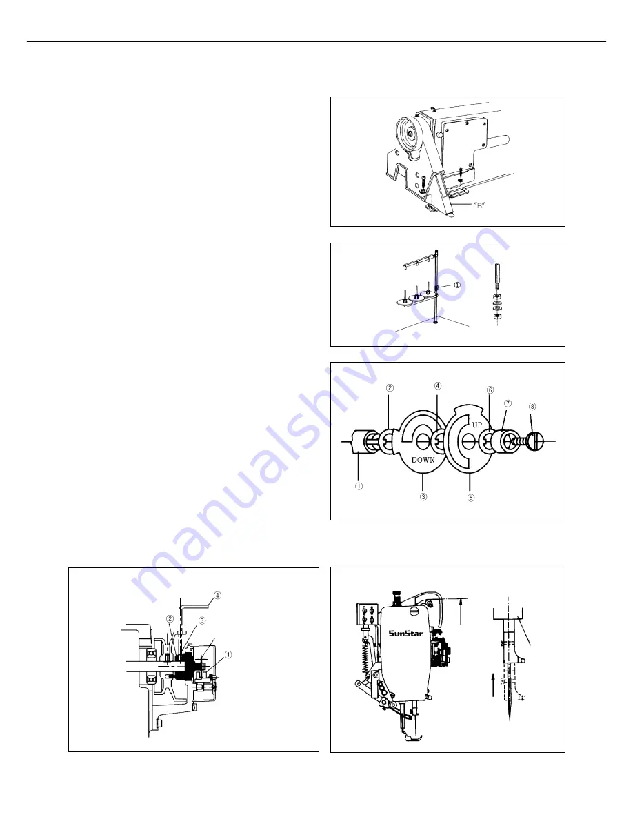
C. Lastly, fasten the belt cover
“
B
”
to the table, as can be
seen in figure 10.
[Figure 10]
8) Installation of the thread stand
As can be seen in figure 11, fix the thread stand
①
to the
table using the washer and nut on the right.
[Figure 11]
9) Location detector assembling and its
control method (automatic trimming type)
(1) Installation of location detector
Assemble in the order of marked number as can be seen in
figure 12. Then, following the figure 13, make adjustments
to place the photo film at the center of the sensor housing
①
,
by moving the shaft
②
right and left. Then, tighten the 2
fixing screws
③
using the hexagonal wrench
④
.
[Note]
a) As can be seen on figure 12, make sure that the
marks
“
DOWN
”
and
“
UP
”
face the front when
looking from the pulley side.
b) Film adjustment is completed upon shipment.
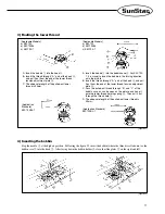
Photo film
(right and left adjustment)
Thread take up lever
up-stop position
Needle bar frame
[Figure 12]
[Figure 13]
[Figure 14]


