background image

Aug 04 

- 20 - 

Form 44080000 


Models 

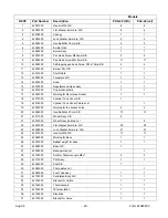
KEY# Part 

Number Description PHS-40 

(S/S) 

PHJ-40 

(Jet) 

44081000 

Hex-Nut M8 S/S 

44082000 

Flat Washer 8mm dia. S/S 

3 44078000  Canopy 

44083000 

Lock Washer 8mm dia. S/S 

44084000 

Hex-Bolt M8x 20mm S/S 

6 44085000  Emitter 

Grid 

7 44086000  Burner 

Assy 

44087000 

Pan Head Screw M4x6mm S/S 

44088000 

Pan Head screw M5×8mm S/S 

17 

17 

10 

44089000 

Self-tapping pan head Screw ST5x 10mm S/S 

11 

44090000 

Burner Pan S/S 

12 44091000  Pilot 

Shield 

13 44092000  Faceplate 

S/S 

14 44093000  Knob 

15 

44079000 

Regulator and Hose Assy 

16 44057000  Cup 

holder-plastic 

17 

44094000 

Molding for Decorative Socket 

18 

44077000 

Cylinder Tank Cover S/S 


18 

44076000 

Cylinder Tank Cover Painted Jet 


19 

44095000 

Molding for the access holes 

20 

44069000 

Hex-Bolt M6x 20mm S/S 

13 

13 

21 

44071000 

Wheel Assy  S/S 


21 

44072000 

Wheel Assy  painted Jet 


22 

44067000 

Flat Washer 6mm dia. S/S 

38 

38 

23 

44068000 

Lock Washer 6mm dia. S/S 

21 

21 

24 

44070000 

Hex-Nut M6 S/S 

17 

17 

25 

44096000 

Molding for Base 

26 

44097000 

Ballast weight for base 

27 44098000  Base 

S/S 


27 

44099000 

Base painted Jet 


28 

44100000 

Nuts for Thermocouple M8x1 

29 44101000  Pilot 

Assy 

30 44064000  Post 

S/S 


30 

44063000 

Post painted Jet 


31 

44065000 

Fuel Tube Assy 

32 

44102000 

Perforated Body S/S 

33 

44103000 

Bracket for Orifice 

34 44104000  Thermocouple 

35 44105000  Wire 

Insulation 

36 44106000  Electrode 

37 

44107000 

Bracket for Valve 

Summary of Contents for PHJ40

Page 1: ...her appliance WARNING FOR YOUR SAFETY For Outdoor Use Only Outside any enclosure Solamente Para Uso En Exteriores Fuera de cualquier recinto WARNING FOR YOUR SAFETY Improper installation adjustment alteration service or maintenance of this product can cause injury or property damage Please read the installation and operating instructions thoroughly before installing or servicing this appliance WAR...

Page 2: ...Aug 04 2 Form 44080000 WARNINGS Read this installation and owners guide carefully before attempting to assemble or operate the heater ...

Page 3: ...nd tank adapter that is supplied with the product Replacements must be those specified by the manufacturer Test all fittings and connections with a soapy solution prior to use Never use an open flame or open flame device Keep water sources such as sprinklers away from the burner and controls Certain items or materials when stored under the heater or too close to the heater head will be subject to ...

Page 4: ... to the cylinder valve Do NOT attempt to alter or modify any parts of this safety system Never attempt to use a cylinder that has a rusted or damaged main body a damaged collar or valve or a damaged foot ring Take your cylinder to an authorized propane retailer if you have any questions about the safety or suitability of your cylinder When the heater is not in use turn the LP tank OFF New tanks wi...

Page 5: ...12 6 44068000 Washer lock M6 SS 8 8 7 44069000 Screw Hex Head SS M6 x 20 mm 4 4 8 44070000 Nut M6 SS 4 4 9 44071000 Wheel Assembly SS 2 9 44072000 Wheel Assembly Painted Jet 2 10 44073000 Base assembly Jet painted 1 10 44074000 Base assembly SS 1 11 44057000 Burner assembly complete 1 1 12 44075000 Cup holder 4 4 13 44076000 Cylinder Cover Jet Painted 1 13 44077000 Cylinder Cover SS 1 14 44078000 ...

Page 6: ...and wheel kit 11mm AF or 7 16 Socket for Ballast Plate 12mm Socket for Canopy Standard Philips head 2 and 3 screwdrivers Channel locks or pliers minimum 1 Capacity Adjustable Crescent wrench or socket driver Soapy water solution for leak testing 4 Lay the base down on its side to disassemble the burner from the base Keep the nuts and washers that are removed They are used to secure the canopy 5 Wi...

Page 7: ...ith the burner upturned remove the plastic caps from the burner gas inlet and the fuel tube Attach the fuel tube to the burner Either end of the fuel tube can be used 7 Lower the post over the fuel tube and attach to the burner ...

Page 8: ...he socket in the base assembly Follow the steps below Step 1 Rotate the post until the holes are aligned with the socket Step 2 Align the sleeve to line up with the holes Step 3 Lower the sleeve over the post holes Step 4 Secure the post using the 4 x M6 x 12mm screws and washers provided ...

Page 9: ...Aug 04 9 Form 44080000 10 Attach the canopy to the burner CAUTION DO NOT attempt to attach the canopy in windy conditions Choose a sheltered area Failure to do so may result in damage to the heater ...

Page 10: ...44080000 11 Lift the cylinder cover and attach hose and regulator assembly to the fuel line CAUTION Before you attempt to use a propane tank understand all tank and Propane related precautions on Page 4 of this manual ...

Page 11: ...er Use only cylinders equipped with an approved OPD Overfill Protection Device This device prevents accidental over filling and possible escape of fuel when the cylinder is heated These OPD equipped cylinders can be easily identified by their triangular handle at the top of the tank and inside and outside threads where the regulator attaches to the cylinder valve Do NOT attempt to alter or modify ...

Page 12: ...onto the connections as illustrated Step 3 Inspect the solution for bubbles If no bubbles appear then the connection is secure If Bubbles appear then there is a leak Turn OFF the cylinder valve Undo the connection and inspect the surface of the cone to make sure they are clean Reconnect using two wrenches on the on either side of the connection Repeat the leak checking procedure described above If...

Page 13: ...e solution for bubbles If no bubbles appear then the connection is secure If Bubbles appear then there is a leak Turn OFF the cylinder valve Release the Regulator connection to the cylinder Re attach the Regulator making sure the connection is tight Repeat the leak checking procedure described above If you continue to see bubbles after several attempts DO NOT use the heater Contact Sunstar heating...

Page 14: ...tdoor patio outdoor decks outdoor spa areas pool areas and other outdoor areas with plenty of fresh air The heater is NOT designed approved or intended for indoor use or enclosed area use such as a garage commercial building tents ice fishing tents prefabricated buildings or enclosures or other enclosed areas The heater is also not designed for use on moving objects or vehicles such as houseboats ...

Page 15: ... Use the diagram below to locate the components referred to in this instruction sequence 1 Raise the cylinder cover to access the LP gas cylinder Turn the valve OFF 2 Push the control knob in and turn to the OFF position 3 Move the cover over the inspection hole 4 Turn the cylinder valve anticlockwise to open 5 Gently depress the gas control knob and turn it anticlockwise to PILOT position Note Fo...

Page 16: ...n in an area sheltered from inclement weather such as rain snow sleet hail dust storms and other blowing debris Sunstar Heating Products makes a cover PN 44033000 available to protect the burner head We strongly recommend using our cover when your heater is in storage or not in use The cover will help protect the heater head from moisture as well as insects CAUTION Allow at least 45 minutes after ...

Page 17: ...osive Never spray any cleaning product on the emitter grid or burner area Painted models Wash all painted parts of the heater with a soapy solution and protect it with a coat of automobile car wax a couple of times per year or as required dependent upon your local weather and climate conditions If you need to touch up a painted heater only paint the post and base portions Never paint the emitter g...

Page 18: ... location Do not use heater in winds in excess of 10 MPH Pilot flame does not touch thermocouple Replace pilot if gas pressure is OK Thermocouple connection at valve may be loose Tighten connection firmly Thermocouple is damaged Replace thermocouple Gas Valve is damaged Replace gas valve Burner Does Not Light Burner orifice clogged Clean or replace orifice Burner orifice not correct size Replace w...

Page 19: ...Aug 04 19 Form 44080000 REPLACEMENT PARTS Replacement Parts Diagram for Models PHS 40 PHJ 40 ...

Page 20: ...for Decorative Socket 1 1 18 44077000 Cylinder Tank Cover S S 1 18 44076000 Cylinder Tank Cover Painted Jet 1 19 44095000 Molding for the access holes 2 2 20 44069000 Hex Bolt M6x 20mm S S 13 13 21 44071000 Wheel Assy S S 2 21 44072000 Wheel Assy painted Jet 2 22 44067000 Flat Washer 6mm dia S S 38 38 23 44068000 Lock Washer 6mm dia S S 21 21 24 44070000 Hex Nut M6 S S 17 17 25 44096000 Molding fo...

Page 21: ...Socket Assy S S 1 1 47 44118000 Socket Assy Painted Jet 48 44066000 Pan Head Screw M6 12 S S 8 8 49 44119000 Orifice for main burner 1 1 50 44120000 Connection tube at Valve Base 1 1 51 44121000 Thermoelectric Control Valve 1 1 52 44122000 Tube assy for Burner 1 1 53 44123000 Compression fitting for Orifice 1 1 Not Shown 44124000 Replacement Screw package for Burner 1 1 Not Shown 44125000 Replacem...

Page 22: ...here gas pressure to each heater is higher than that specified for each heater b to circumstances where the type of gas is different than the type of gas noted on the name plate for each heater c to water damage to gas controls and d to any heater or component which has been repaired or replaced with other than factory parts modified in any way misused or damaged or which have been used contrary t...

Page 23: ...Form 44080000 SUNSTAR HEATING PRODUCTS Post Office Box 36271 28236 306 West Tremont Avenue 28203 Charlotte North Carolina Phone 704 372 3486 Fax 704 332 5843 Toll Free 888 778 6872 e mail info sunstarheaters com ...

Reviews: