background image

-7- 

INSTALLATION TO GAS SUPPLY 


1.  The  gas  supply  must  comply  with  local  codes,  or  in  their 

absence,  the  installation  must  be  in  accordance  with  the 
American National Standard (National Fuel Gas Code) NFPA 
54,  also  known  as  ANSI  Z223.1  -  latest  edition,  available 
from  the  ANSI,  Inc.,  1434  Broadway,  New  York,  New  York 
10018,  or  the  National  Fire  Protection  Association, 
Batterymarch Park, Quincy, MA  02269. 


2. 

WARNING:

    When  using  LP  gas,  this  heater  requires  an 

external regulator (not supplied) located between the heater 
and LP Supply Tank.  This regulator must be supplied by the 
installer to reduce incoming LP Gas pressure to a maximum 
of  14  inches  of  water  column.  Under  no  circumstances 
should  this  heater  ever  be  hooked  directly  to  an  LP  supply 
tank.   

IMPORTANT:

    The  Pressure  Regulator  must  be  held 

with a wrench when connecting gas piping and/or fittings to 
the Pressure Regulator. 


3.  Use only new, black iron or rust resistant steel pipe. Copper 

tubing  may be acceptable  in certain areas.  

CHECK LOCAL 

CODES  TO  DETERMINE  ACCEPTABLE  TYPES  OF  GAS 
PIPING.


4.  The gas supply line shall be sized and installed to provide a 

sufficient  supply  of  gas  to  meet  the  minimum  demand  of 
the heater without undue loss of pressure. 


Typical Installation 

Supply Line 

Up to 20,000 Btu/hr 

3/8" or greater 

Up to 30,000 Btu/hr 

1/2" or greater 


5.  The sealant used on the threaded pipe joints of the gas pipe 

must  be  the  specific  type  resistant  to  the  action  of  Liquid 
Petroleum  Gas.    Apply  sealant  lightly  to  male  threads  to 
ensure  excess  sealant  does  not  enter  lines.  Any  excess 
sealant  could  be  forced  into  the  pipe  and  result  in  clogged 
gas valves. 


6.  The supply system must include a manual shut-off valve, a 

union  in  the  line,  and  a  plugged  1/8"  NPT  tap.    The  tap 
should be accessible for test gauge connections upstream of 
the gas supply connection to heater. 


7.  Include  a  drip  leg  (trap)  in  the  supply  line.    The  purpose  of 

the drip leg is to prevent moisture and contaminants in the 
gas  supply  from  entering  the  heater  controls.    The  drip  leg 
should be readily accessible to permit cleaning or emptying.  
A  drip  leg  should  not  be  located  where  the  condensate  is 
likely  to  freeze.    Failure  to  use  a  drip  leg  can  result  in 
operational difficulties in the heater. 


GAS SUPPLY CHECK 


A union must be provided directly at the gas inlet to the heater.  
A  manual  gas  valve  must  be  provided  upstream  of  the  union.  
This will allow you to shut off the gas supply to the heater if it is 
necessary to remove it for service purposes. 


The  appliance  and  its  appliance  main  shutoff  valve  must  be 
disconnected  from  the  gas  supply  piping  system  during  any 
pressure  testing  of  that  system  at  test  pressures  in  excess  of 
1/2 psig. (3.45kPa). 


The  appliance  must  be  isolated  from  the  gas  supply  piping 
system  by  closing  its  equipment  shutoff  valve  during  any 
pressure testing of the gas supply piping system at test pressures 
equal to or less than 1/2 psig. (3.45kPa). 


The connectors must be checked and cleaned before assembling 
and then wrenched up tight for a gas tight connection.  Apply a 
soap  and  water  solution  to  all  joints  and  watch  for  bubbles  to 
check for gas leaks. 

 NEVER USE ANY OPEN FLAME TO CHECK 

FOR GAS LEAKS. 

HEATER MAINTENANCE - PERIODIC VISUAL CHECK 


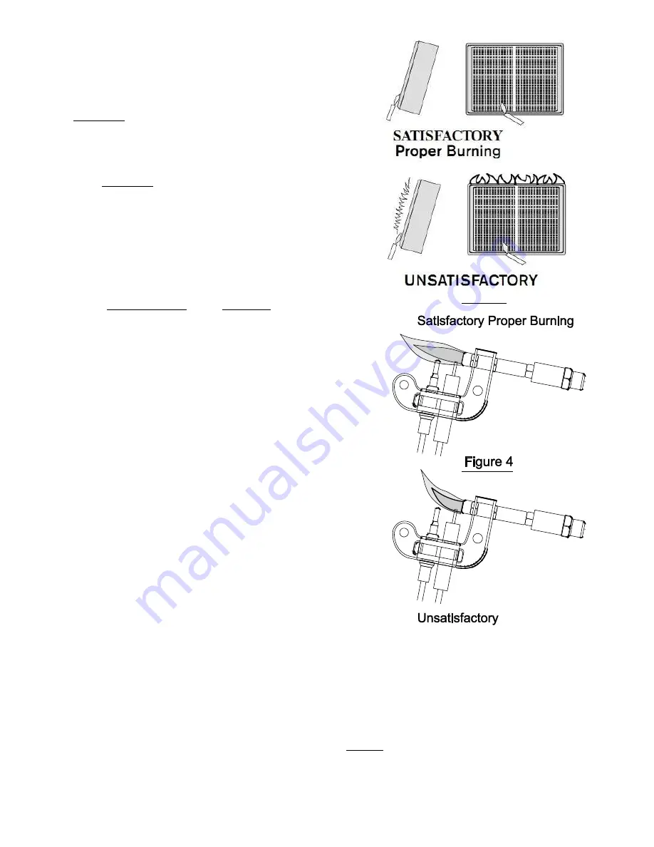
The  burner  must  glow  evenly  over  the  entire  surface  when 
operating correctly.  The pilot flame must burn with a clear blue 
flame.  See Figures 3 and 4.


HEATER SERVICE


To service the heater, turn off the gas supply and disconnect the 
gas piping at the union.  Unscrew the two screws located in the 
lower  front  part  of  the  unit.    By  sliding  the  panels  upwards  and 
toward  the  front,  the  functional  elements  of  the  unit  are 
uncovered. 


Periodic cleaning of the unit is required.  Dust the surface of the 
unit  and  vacuum  clean  burner  surfaces  and  the  control 
compartment. 


BURNER 

If  this  heater  has  an  optional  blower,  disconnect  the  electrical 
connection before servicing the heater (e.g., unplug the blower). 


Keep the heater area clear and free from combustible materials, 
gasoline and other flammable vapors and liquids. 


Figure 3 

Summary of Contents for SC10M-1-LP

Page 1: ...ance CONSUMER Retain this manual for future reference This is an unvented gas fired heater It uses air oxygen from the room in which it is installed Provisions for adequate combustion and ventilation air must be provided Refer to the section titled Combustion and ventilation air requirement Do not store or use gasoline or other flammable vapors and liquids in the vicinity of this or any other appl...

Page 2: ...000 ft because shutdown of the heater by the ODS system may occur due to reduced oxygen levels at these altitudes 5 This appliance is only for use with the type of gas indicated on the nameplate THIS APPLIANCE IS NOT CONVERTIBLE FOR USE WITH OTHER GASES Please check the gas type shown on the heater nameplate prior to hooking the heater to the gas supply 6 DO NOT install this heater in bathrooms Th...

Page 3: ...ut rating of all gas equipment in the space 18 This heater shall not be installed in a room or space unless the required volume of indoor combustion air is provided by the method described in the National Fuel Gas Code ANSI Z223 1 NFPA 54 the International Fuel Gas Code or applicable codes 19 WARNING If the area in which the heater may be operated does not meet the required volume for indoor combu...

Page 4: ..._ x 20 Btu hr ____________________ Btu hr STEP 3 Add the Btu hr inputs of all fuel burning appliances in this space NOTE DO NOT include Direct Vent gas appliances because these have sealed combustion systems that draw combustion air from outdoors Examples of appliances to consider include gas ranges gas water heaters gas logs kerosene heaters etc Proposed Vent Free Heater _________________________...

Page 5: ... odorant in escaped gas can adsorb or absorb onto or into walls masonry and other materials and fabrics in a room That will take some of the odorant out of the gas reducing its odor intensity LP Gas may stratify in a closed area and the odor intensity could vary at different levels Since it is heavier than air there may be more odor at lower levels Always be sensitive to the slightest gas odor If ...

Page 6: ... the heater the clearance from any combustible materials must be a minimum of 10 from the left 10 from the right 36 from the top and 2 from the bottom Never install the heater in front of any flammable object especially do not place curtains furniture clothing or other flammable objects less than 36 from the front of the heater FLOOR MOUNT INSTALLATION When using the optional legs for Models SC10M...

Page 7: ...according to the dimensions shown on the upper corner of Figure 2 1 3 Drill another 5 16 hole on the wall stud for the lower mounting point 4 Screw in the three 3 plastic expansion anchors furnished with the unit as shown in Figure 2 1 5 Screw in the furnished screws to the anchors for the upper mounting points and hang the heater on the screws as shown in Figure 2 1 6 Fasten the bottom of the hea...

Page 8: ...revent moisture and contaminants in the gas supply from entering the heater controls The drip leg should be readily accessible to permit cleaning or emptying A drip leg should not be located where the condensate is likely to freeze Failure to use a drip leg can result in operational difficulties in the heater GAS SUPPLY CHECK A union must be provided directly at the gas inlet to the heater A manua...

Page 9: ...to the pilot assembly Remove the cover and blow any dust out Reassemble and check for proper operation If that fails the pilot assembly should be removed and air blown through the assembly and gas line as shown in Figure 6 To prevent damage to this assembly follow the instructions below for disassembly and assembly of the ODS for cleaning WARNING Never use needles wires or similar cylindrical obje...

Page 10: ...til pilot is lit Setting OFF OFF 1 2 P Pilot Burner Setting P OFF 1 2 P Pilot Burner 6 Continue depressing control knob for 30 seconds after pilot is lit before releasing If knob does not pop up when released stop and inmediately call your service technician or gas supplier 7 Pilot should remain lit If the pilot will not stay lit after several tries turn the gas control knob to OFF and call your s...

Page 11: ...gas valve BURNER DOES NOT LIGHT Pilot stays lit Burner orifice clogged Burner orifices not correct size Extremely low inlet gas pressure Gas valve is defective Clean or replace orifices Replace with correct size Contact gas supplier Replace gas valve IMPROPER BURNER PATTERN Slight smoke or odor during initial operation Residues from manufacturing process or dust Problem will be eliminated after a ...

Page 12: ...ater so that the solid portion of the base is facing towards the front of the heater using four 4 No 10 x 1 screws provided 4 Attach a field supplied pipe elbow 3 8 NPT thread to the bottom of the heater for connection to the gas line as shown in the figure below and as instructed previously in these instructions WARNING This heater must be installed on a wall whenever it is installed in a bedroom...

Page 13: ...10M 1 LP Propane Gas SC10M 1 NG Natural Gas WARNING Failure to position the parts in accordance with these diagrams or failure to use only parts specifically approved with this heater may result in property damage or personal injury ...

Page 14: ...LS SC10M 1 LP Propane Gas SC10M 1 NG Natural Gas WARNING Failure to position the parts in accordance with these diagrams or failure to use only parts specifically approved with this heater may result in property damage or personal injury ...

Page 15: ... 43597080 43597080 Screw 4 43708030 43708030 Spacer Out 5 43597140 43597140 Screw 6 43584160 43584170 ODS System 7 43576100 43576110 Regulator 8 43597110 43597110 Screw 9 43590050 43590050 Connector 10 43596070 43596070 Control Valve 11 43585770 43585770 Tubing Regulator to Tap 12 43585790 43585790 Tubing Tap to First Setting 13 43585800 43585800 Tubing Tap to Second Setting 14 43585330 Tubing Tub...

Page 16: ...15 Manufactured for SUNSTAR HEATING PRODUCTS INC 306 West Tremont Avenue Charlotte NC 28203 4946 704 372 3486 ...

Reviews: