15
55
PREPARATION BEFORE USING THE MACHINE
1) Setting the Voltage
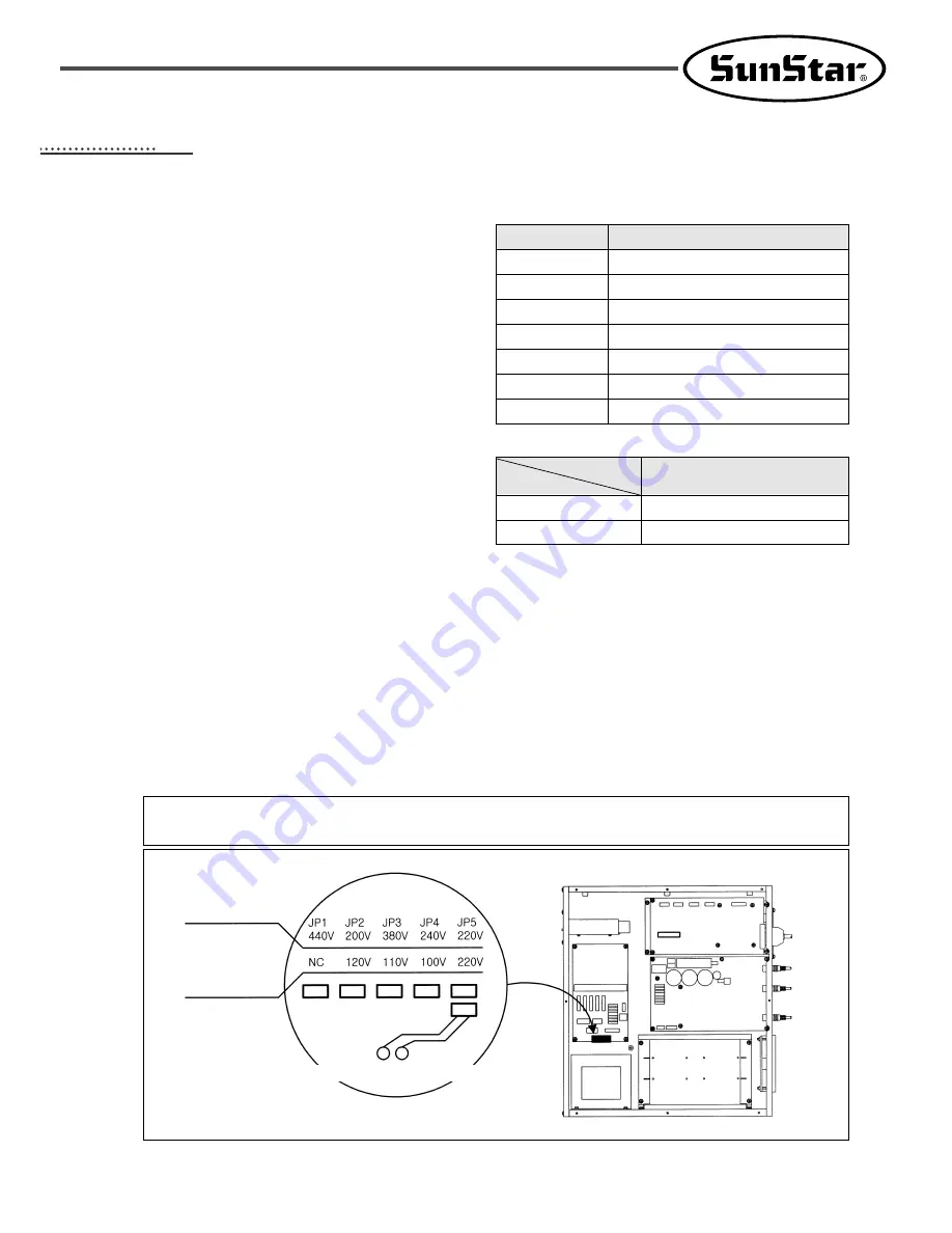
A. If a cover of electronically controlled pattern
sewing machine is taken off, inside contents
are as same as [Fig. 7].
B. Confirm the position of change connector of
power voltage on power board [Refer Fig. 1]
and transformer if they are properly selected
for input voltage like Table 1 and 2.
EX) If power voltage is 220 V:
The model of used transformer is “SPS-
-
220”and it is normal for the
change connector of power voltage to be
placed on “JP5”.
※ Sticker for transformer model is attached to
the top side of transformer.
C. Check if a power switch is for 1 phase and 3 phase.
D. If the setting of B and C is not proper, damage from breakdown can be occurred. If there is any
problem, follow below direction.
ⓐ If the position of change connector is wrongly placed :
① Separate the connector linked to transformer from CN7, CN8 and CN9 of power borad.
② Insert the power change connector into a proper position on Table 1.
③ Reconnect the connector linked to transformer to CN7, C8 and CN9 of power board.
ⓑ If the specification of used transformer is not in a accord with that of power switch, ask to the
place where you purchased for troubleshooting.
[ Table 1. Position of change connector of voltage ]
[ Table 2. Model of used transformer according to
the input power voltage ]
[ Setting of change connector of power voltage ]
[ Fig. 7 ]
[ Caution ]
Before turning on the power switch, air should be filled with.
If an Input Power
Voltage is Over 220V
If an Input Power
Voltage is 110V
Change Connector of Power Voltage
Floppy
Disk Drive
Power
Board
Step Motor
Drive Board
Main Shaft
Motor Drive Board
Control Box
CPU+IO
Board
Cooling Pan
Transformer
Input voltage
95V~105V
106V~115V
116V~125V
200V~230V
231V~245V
345V~415V
416V~480V
Position of change connector of power voltage
JP4
JP3
JP2
JP5
JP4
JP3
JP2
110V~120V
220V~440V
″SPS-5030~110″
″SPS-5030~220″
Power Voltage
Model
SPS/A-5030-XX-XX


