16
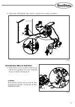
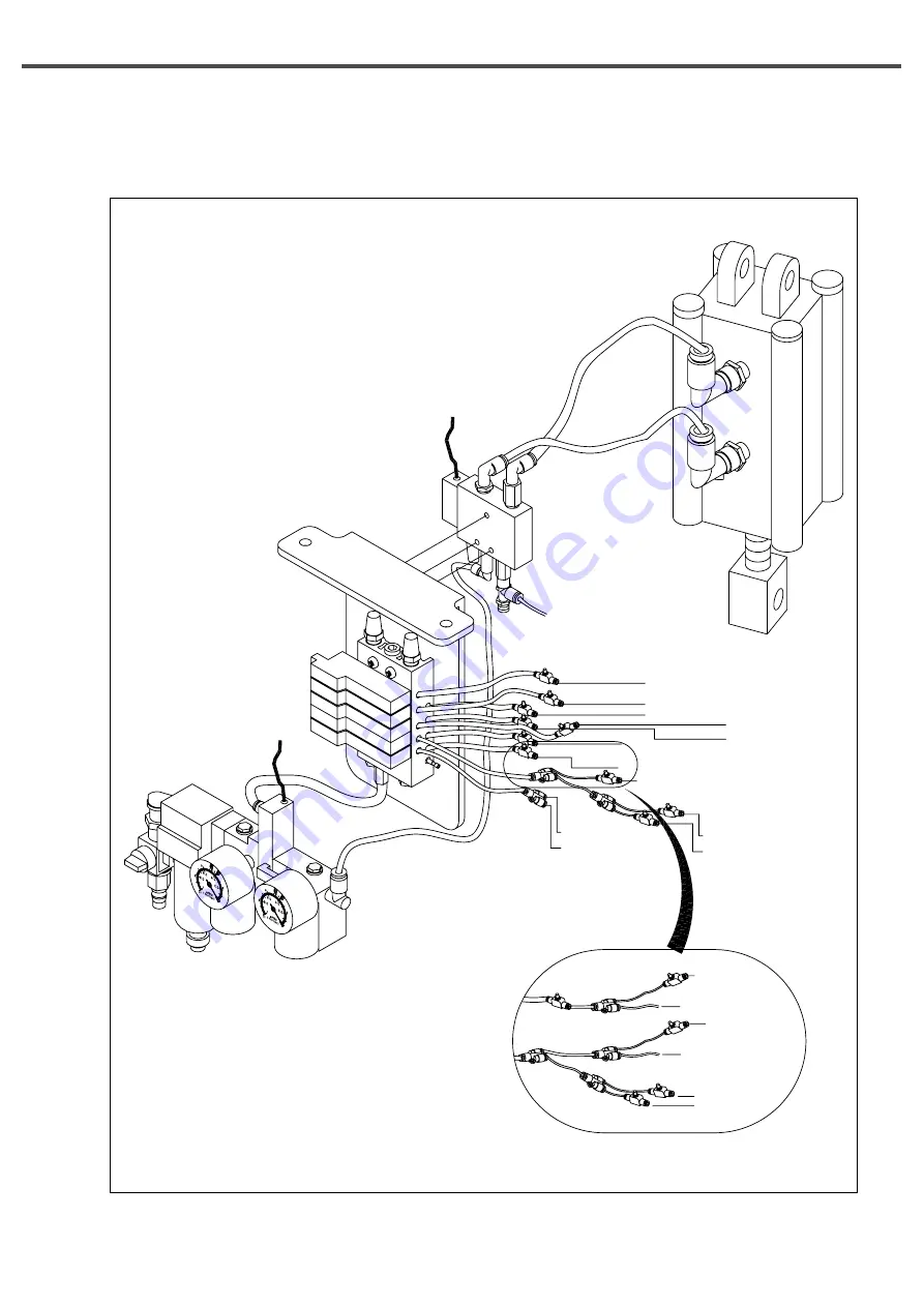
C. Connect air hoses, which are linked to the machine, to solenoid valves.
[ Fig. 7 ]
01 Model
Cutter (rear) (17)
Cutter (front) (16)
Cutter bracket (15)
Upper thread trimmer (front) (9)
Thread controller (rear) (7)
Upper thread trimmer (rear) (10)
Lower thread trimmer (rear) (5)
Thread controller (front) (8)
Lower thread trimmer (front) (6)
Safety plate (front) (12)
Safety plate (rear) (11)
Presser plate (left) (2)
Presser plate (right) (1)
Cloth opening (left) (4)
Cloth opening (right) (3)
Safety plate (front) (12)
Auxiliary clamp (front)(13)
Safety plate (rear) (11)
Cloth opening (left) (4)
Cloth opening (right) (3)
Auxiliary clamp (rear) (14)
02 Model
Summary of Contents for SPS/D-BH-6000 Series
Page 37: ...37 8 8 Table Drawings 1 Basic ...
Page 38: ...38 2 Optional Mountable on the table ...
Page 42: ...42 1 10 0 Air System Circuit Diagram ...
Page 43: ...43 ...
Page 44: ...44 Optional Devices ...


