17
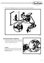
[ Fig. 9 ]
6) Connecting cables to control box
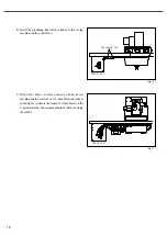
A. Lift the machine as much as possible as in the figure and
make the head supporting lever axis (B)
①
inserted into
the groove of the head supporting lever
②
.
①
②
[ CAUTION ]
When lifting the machine, make sure that the head
supporting lever axis(B) is inserted into the head
supporting lever groove.
[ Fig. 8 ]
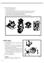
D. Connect cables, which are linked to the control box, to solenoid valves according to each number .
Control box
Summary of Contents for SPS/D-BH-6000 Series
Page 37: ...37 8 8 Table Drawings 1 Basic ...
Page 38: ...38 2 Optional Mountable on the table ...
Page 42: ...42 1 10 0 Air System Circuit Diagram ...
Page 43: ...43 ...
Page 44: ...44 Optional Devices ...


