background image

41

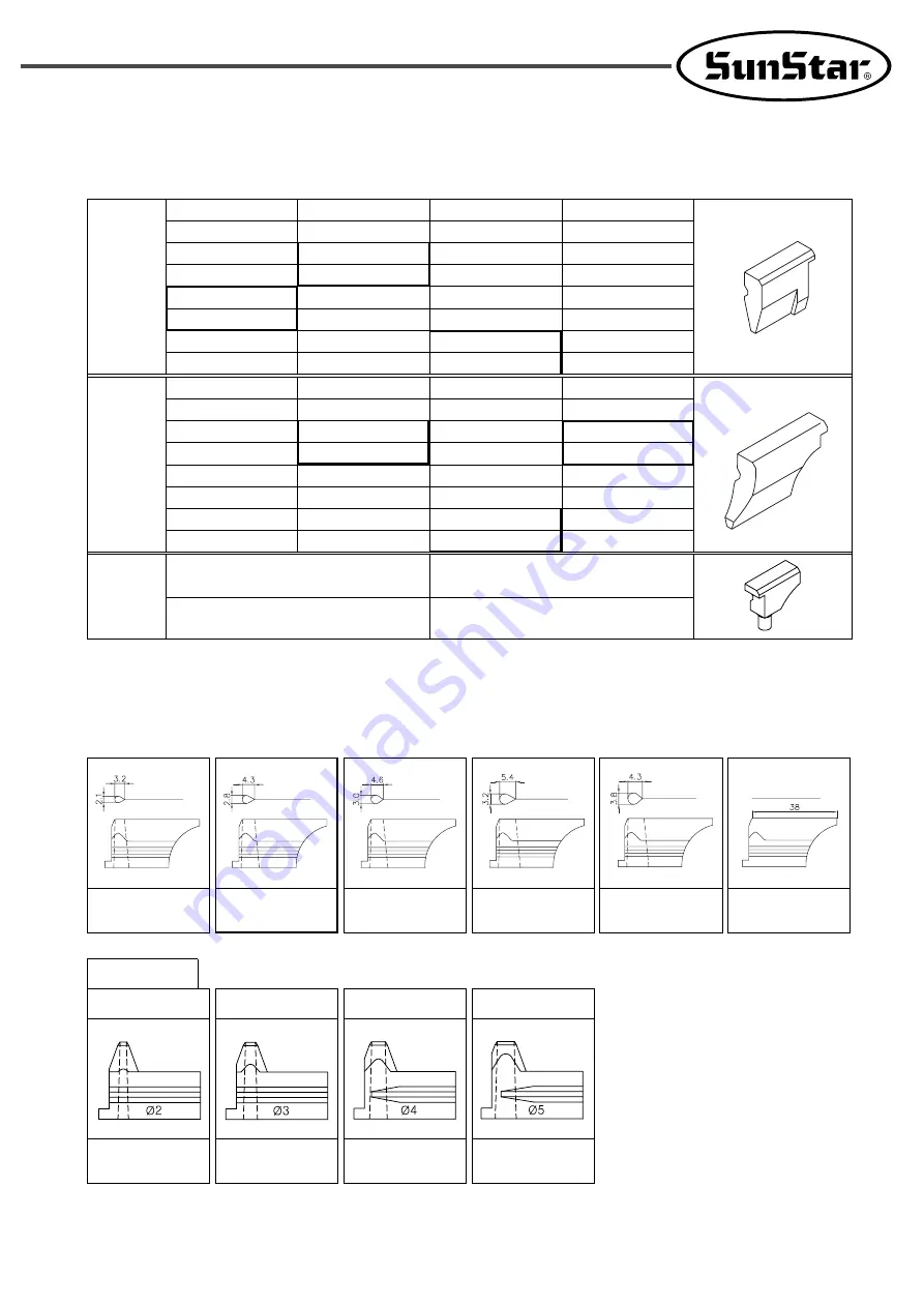
3) Hammer

4) Cutter

-01

-02

S10mm

GP-002281

S18mm

GP-002285

S26mm

GP-002287

34mm

GP-002278

Circular

Hole

ф5

GP-007893

ф7

GP-011919

S12mm

GP-002282

S20mm

GP-001701

S28mm

GP-002288

36mm

GP-002279

S16mm

GP-002284

S24mm

GP-001702

32mm

GP-002277

S14mm

GP-002283

S22mm

GP-002286

30mm

GP-002276

38mm

GP-001006

10mm

GP-002268

18mm

GP-002272

26mm

GP-001019

34mm

GP-002278

12mm

GP-002269

20mm

GP-001018

28mm

GP-002275

36mm

GP-002279

14mm

GP-002270

22mm

GP-002273

30mm

GP-002276

38mm

GP-001006

16mm

GP-002271

24mm

GP-002274

32mm

GP-002277

GP-002258

GP-001011

GP-002259

R:GP-011907

ф2

R:GP-007895

R:GP-007896

GP-002260

R:GP-011920

GP-002261

GP-002262

Circular Hole

ф3

ф4

ф5

Summary of Contents for SPS/D-BH-6000 Series

Page 1: ... SPS D BH 6000 Series Direct Drive Electronically Controlled Eyelet Button Hole Sewing Machine 1 For proper use of the machine thoroughly read this manual before use 2 Keep this manual in a safe place for future reference in case the machine breaks down M MM ME E 0 06 60 03 33 31 1 ...

Page 2: ... functions high performance powerful operation enhanced durability and more sophisticated design to meet a number of user s needs 2 Please read this user s manual thoroughly before using the machine Make sure to properly use the machine to enjoy its full performance 3 The specifications of the machine are subject to change aimed to enhance product performance without prior notice 4 This product is...

Page 3: ...DirectDrive ElectronicallyControlledEyeletButtonHoleSewingMachine SunStar Pattern System Series Model Name Thread Trimming Type 01 Long Trimming 02 Short Trimming SPS D BH6000 ...

Page 4: ...ox 17 5 Preparations before Operating the Machine 19 1 Lubrication 19 2 Attach Needles 20 3 Place Upper Thread 21 4 Place Lower Thread 21 5 Place Inside Thread 22 6 Adjust Thread Tension 22 7 Adjust Sewing Margin 24 8 Handle Used Oil 24 6 Maintenance and Repair 25 1 Adjust the Height of Spreader and Looper 25 2 Adjust the Timing of Needle and Looper 26 3 Adjust Looper Stroke 27 4 Adjust the Height...

Page 5: ...2 Adjust Sewing Margin 48 3 Adjust the Position of Cloth Transfer Plate Left 49 4 Adjust the Speed of Cloth Transfer 49 5 Adjust the Original Position of Cloth Transfer Bar 49 6 Adjust the Gap between Holes 50 7 Adjust Limit Switch Left 51 8 Adjust Limit Switch Right 51 2 Special Lapel Cutter 52 1 Install Special Lapel Cutter 52 2 Install Solenoid Valve 53 3 Adjust the Position of Button Hole Sens...

Page 6: ...ser could prevent expected malfunction Caution Warning Danger Only skilled persons who have the knowledge of safety guide and rules are allowed to transport this machine The followings shall be kept in mind during transportation ⓐ More than two people are required to move the machine ⓑ To prevent any safety related accidents during transportation thoroughly wide off the oil spread on the surface o...

Page 7: ...multiple motors into one electric outlet ⓙ Grounding system must be connected ⓚ Place the machine away as far as possible from noise generated sources including high frequency welding machine 3 Operation Caution Depending on installation environments functional errors breakdown and other physical damages could occur to the machine The following conditions shall be satisfied for the installation ⓐ ...

Page 8: ...bitrary change of the machine could cause dangers during operation ⓒ Use the spare parts produced by Sunstar for repairing ⓓ Put safety covers which are removed for repair back to the machine after the repairing is done 4 Repair Caution 5 Safety Devices ⓐ Safety label Cautions during machine operation ⓑ Motor cover Prevents potential accidents which might occur during motor operation ⓒ Inside thre...

Page 9: ...ch 손가락 보호대와 안전장치 없이 작동하지 마십시오 실 보빈 바늘교환시나 청소전에는 반드시 주전원의 스위치를 꺼 주십시오 CAUTION 경 고 Do not operate without finger guard and safety devices Before threading changing bobbin and needle cleaning etc switch off main switch 손가락 보호대와 안전장치 없이 작동하지 마십시오 실 보빈 바늘교환시나 청소전에는 반드시 주전원의 스위치를 꺼 주십시오 WARNING 경 고 Hazardous voltage will cause injury Be sure to wait at least 360 seconds before opening this cover after t...

Page 10: ...edle cleaning etc switch off main switch 손가락 보호대와 안전장치 없이 작동하지 마 십시오 실 보빈 바늘교환시나 청소전에는 반드시 주전원의 스위치를 꺼 주십시오 WARNING 경 고 Hazardous voltage will cause injury Be sure to wait at least 360 seconds before opening this cover after turn off main switch and unplug a power cord 고압 전류에 의해 감전될 수 있으므로 커버 를 열 때는 전원을 내리고 전원 플러그를 뽑 고 나서 360초간 기다린 후 여십시오 CAUTION 경 고 ...

Page 11: ...5 2 0mm Schmetz 558 DO 558 Nm90 Nm80 Nm120 Schmetz 558 DO 558 Nm110 Nm80 Nm120 12mm 16mm 0 5MPa 5Kgf cm2 600VA 1 phase 100 240V 3 phase 200 440V Direct drive type 500W AC servo motor 1 Pulse motor 3 0 20mm Special Lapel Cutter Fly Indexer Upper Thread Holder Upper Thread Holder Foot Switch Foot Switch Mountable on the Table Mountable on the Table 10 38mm Jeans working clothes Short Trimming 14 40m...

Page 12: ...12 3 3 Components of the Machine 1 Name of components Arm Operation Box Thread Stand Emergency Switch Hand Switch Safety Plate Power Switch Control Box ...

Page 13: ...e separate power supply from strong magnetic and high frequency electric goods It will be better to put them away from each other C When attaching peripherals and accessories to Control Box make sure of using low voltage which is safe D Do not spill water or coffee into Control Box and motor E Do not drop Control box and motor Caution Only trained technicians shall install the sewing machine You c...

Page 14: ...fety accidents at least two persons shall handle the machine to place it on top of the table Fig 3 4 Assembling accessories A Fix the rubber washer the oil container holder and the oil container below the bed base Fig 1 3 Placing the machine on top of the table A Attach the table support plate front and the table support plate rear to the table with bolts washers and nuts B Attach the control box ...

Page 15: ...Fig 6 5 Installing pneumatic parts A Attach the filter regulator to the rear side of the table legs using bolts and nuts B Attach the solenoid valve to a proper place on the back of the table using fixing screws Fig 4 B Fix the hand switch to the bed ...

Page 16: ...ar 7 Upper thread trimmer rear 10 Lower thread trimmer rear 5 Thread controller front 8 Lower thread trimmer front 6 Safety plate front 12 Safety plate rear 11 Presser plate left 2 Presser plate right 1 Cloth opening left 4 Cloth opening right 3 Safety plate front 12 Auxiliary clamp front 13 Safety plate rear 11 Cloth opening left 4 Cloth opening right 3 Auxiliary clamp rear 14 02 Model ...

Page 17: ...pporting lever axis B inserted into the groove of the head supporting lever CAUTION When lifting the machine make sure that the head supporting lever axis B is inserted into the head supporting lever groove Fig 8 D Connect cables which are linked to the control box to solenoid valves according to each number Control box ...

Page 18: ...ox Fig 10 C When the cables are fully connected between the machine and the control box fix them below the table as in the figure estimate the length of cables based on the consideration that the machine should be lifted for fixing the cables Fig 11 Control box Control box Grounding line ...

Page 19: ...oil inlet around the arrow to feed oil into the machine Fig 13 B Erect the machine and supply oil to the oil tank installed on bed until the oil reaches the marked line of the tank Fig 14 C Fall 2 3 drops of oil on the needle guard around the upper Arm everyday CAUTION When using the machine first time or when leaving the machine unused for a long term oil supply is a must ...

Page 20: ...de of the bushing ⓖ Bring down the body of the machine and put the cloth press plate back to its place Fig 15 2 Attach needles A Lift the finger guard B Turn the hand pulley and move it to the highest position of the needle bar C Remove the cloth press plate and check whether the punched mark of the looper base and that of the looper base bushing meet together D Release the fixing screw of the nee...

Page 21: ...21 3 Place upper thread As shown in the figure below hang the upper thread Fig 17 4 Place lower thread As shown in the figure below hang the lower thread Fig 18 ...

Page 22: ...ad tension As displayed in the figure turn the tension adjusting nut of the thread adjusting device clockwise and the upper thread tension gets stronger If it is turned counter clockwise the tension gets weaker The tension should be adjusted depending on the threads used and the sewing materials Fig 20 01 Model 02 Model ...

Page 23: ...in the above table are measured when the lower thread is taken out through the thread hole on the needle plate figure b Fig 21 C Adjust thread take up spring tension and movement ⓐ Release screw and turn the lower thread supporting spring plate in the direction of the arrow and the tension of take up spring will increase ⓑ Release screw and turn the lower thread supporting spring guide in the dire...

Page 24: ...se the screw and move the left and right cloth guides to adjust sewing margin Fig 23 Fig 24 8 Handle used oil When the oil container at the bottom of the bed base is filled with used oil empty the oil container CAUTION While removing the oil container oil contents could spill to the floor It would be better to place cloth paper or oil container on the floor 10 30mm ...

Page 25: ...f spreader ⓐ Adjust the left and right spreaders to make them move smoothly ⓑ Loosen the screw and make adjustment by changing the height of the left and right spreader stopper At the proper height tighten the screw Fig 25 B Height of looper ⓐ Set the gap between spreader left and looper left at the thickness of the lower thread ⓑ Set the gap between spreader right and looper right at the minimum ...

Page 26: ...easurements as in C E When adjustment is needed turn the looper base in the direction of the arrow as in the picture Then loosen the screw and move the looper link clamp up and down to move the LS holder bracket left and right in the direction of the arrow Fig 27 Fig 28 CAUTION If the needle is at the left side the end of the looper left shall be set at the center of the needle If the needle is at...

Page 27: ...f the left looper is touching the center of the needle D Repeat the above procedures to check whether the end of the right looper is touching the center of the needle in case where the needle is at the right side E If the end of the looper doesn t meet the center of the needle lift the body of the machine F Loosen the two screws of the lower axle timing belt hold the hand pulley to fix it and then...

Page 28: ...mp and the needle bar horizontal link to maintain their own oil layers respectively 5 Adjust the distance between needle and looper Loosen the looper screw to adjust the distance between needle and looper at the range of 0 05 0 2mm and then tighten the screw again Fig 31 Fig 32 Make the end of the looper left meet the upper edge of the needle hole and lower the needle bar by 2mm CAUTION Although t...

Page 29: ... needle guard Fig 33 7 Adjust the position of spreader A Loosen the screw and adjust the spreader stopper left to make the fork of the spreader left meet the lower thread guide hole of the looper left B Loosen the screw to make the both ends of the spreader right and the looper right located at the same place and adjust the position of the spreader stopper right Fig 34 ...

Page 30: ...ng nut moves up the stitch length gets narrower and vice versa When shipped out from factory the default stitch length is 2 5mm Fig 35 9 Adjust cloth opening A Loosen the screw and insert a driver through the side groove of the X Y transfer base Turn the adjusting screw for size adjustment B Tighten the screw and measure the size of the opening 0 8mm is ideal Fig 36 1 5 3 2mm 2mm 3mm ...

Page 31: ...osen the screw and remove the hammer B Push new hammer into the pin and tighten the screw Fig 37 11 Replace cutter A Loosen the screw and remove the cutter B Insert new cutter into the cutter stopper and fasten the screw Fig 38 ...

Page 32: ... to the appropriate level as displayed on the pressure gauge and then put the adjusting handle back to its original position B Set the pressure of the main adjusting device at 0 5MPa and that of the cutter adjusting device at 0 3MPa Fig 39 13 Adjust upper thread trimming A 01 Model ⓐ Adjust the upper thread trimming mes to cut only one among the threads in front of the looper right Fig 40 B 02 Mod...

Page 33: ... thread trimming arm is running at full speed the punched mark of the lower thread trimming copper mes shall contact the end of the lower thread trimming fixed mes ⓓ If the thread holder upper and the thread holder center are separated make them closely located by adjusting the thread holder upper washer back and forth Fig 42 B 02 Model ⓐ Use the thread cover to separate the lower thread from the ...

Page 34: ...rew and move the inside thread guide in the direction of the arrow for length adjustment Fig 44 16 Auxiliary clamp arm 02 Model When the clamp moves up the trimming of the lower thread and the inside thread begins In order to ensure that sufficient thread is left after thread trimming the auxiliary clamp prevents sewing cloth from moving during thread trimming Fig 45 ...

Page 35: ...elated parts The curved needle is used The tension of the thread adjusting device s spring is either too excessive or weak The distance of the needle and the looper is different The distance of the needle and the needle guard is different The tip of the looper is worn out Adjust belt tension and replace the belt Check the disconnection of the main shaft motor drive fuse inside the control box and ...

Page 36: ... thread trimming copper mes and the groove of the fixed mes blade are worn out The weak air pressure of the lower thread trimming cylinder prevents proper operation of the upper thread trimming copper mes Wrong placement of the lower thread trimming copper mes The cutter pressure is weak The poor contact of cutter and hammer The blade of the cutter is worn out Replace it with a new one Adjust air ...

Page 37: ...37 8 8 Table Drawings 1 Basic ...

Page 38: ...38 2 Optional Mountable on the table ...

Page 39: ...L GP 000978 R GP 000987 38mm L GP 002220 R GP 002221 A 14 18mm L GP 002244 R GP 002245 B 18 22mm L GP 002246 R GP 002247 C 22 26mm L GP 001694 R GP 001695 D 26 30mm L GP 002248 R GP 002249 E 28 32mm L GP 002250 R GP 002251 F 32 36mm L GP 002252 R GP 002253 G 36 40mm L GP 002254 R GP 002255 01 02 ф5 L GP 007887 R GP 007889 ф7 L GP 011923 R GP 011924 Circular Hole ...

Page 40: ...2 B 18 22mm L GP 002234 02 R GP 002235 02 C 22 26mm L GP 001690 03 R GP 001689 02 D 26 30mm L GP 002236 02 R GP 002237 02 E 28 32mm L GP 002238 02 R GP 002239 02 F 32 36mm L GP 002240 02 R GP 002241 02 G 36 40mm L GP 002242 02 R GP 002243 02 01 02 ф5 L GP 007890 R GP 007892 ф7 L GP 011921 R GP 011922 Circular Hole ...

Page 41: ... GP 002277 S14mm GP 002283 S22mm GP 002286 30mm GP 002276 38mm GP 001006 10mm GP 002268 18mm GP 002272 26mm GP 001019 34mm GP 002278 12mm GP 002269 20mm GP 001018 28mm GP 002275 36mm GP 002279 14mm GP 002270 22mm GP 002273 30mm GP 002276 38mm GP 001006 16mm GP 002271 24mm GP 002274 32mm GP 002277 GP 002258 GP 001011 GP 002259 R GP 011907 ф2 R GP 007895 R GP 007896 GP 002260 R GP 011920 GP 002261 G...

Page 42: ...42 1 10 0 Air System Circuit Diagram ...

Page 43: ...43 ...

Page 44: ...44 Optional Devices ...

Page 45: ...ation ⓐ Take out the air hose and insert the plug into the joint Remove the auxiliary clamp arm and the operating cylinder clamp link Fig 1 ⓑ Remove the fastening screw two screws of the transfer base cover left and install the transfer base left Fig 2 ...

Page 46: ...fer base right Fig 3 ⓓ Insert the cloth transfer bar between the rollers of the cloth transfer guides left right Fig 4 CAUTION Make sure whether the transfer pin slides smoothly into all the holes of the cloth transfer bar If it is not smooth adjust the position of the left and right transfer bases ...

Page 47: ...read trimming cover plate C and the press plate cover B Fig 5 C Install solenoid valve ⓐ Install the manifold bracket on the lower part of the table using the screw ⓑ Remove the plug of the main solenoid valve and attach the joint ⓒ Use the air hose ф6 to connect the joint and the nipple Fig 6 D Connect air hoses Air hoses can be connected to the solenoid valve respectively as shown in this figure...

Page 48: ...right cloth setting guides Make sure that the end of the sewing material touches the left end of the cloth setting guide ⓑ Loosen the fastening screw to adjust the position of the cloth setting guides left right and set the vertical sewing margin at either 9 21mm A D or 9 11mm E G ⓒ Loosen the fastening screw to adjust the position of the cloth setting guides and set the horizontal sewing margin a...

Page 49: ...the number of holes Refer to the table to install the cloth transfer plate 4 Adjust the speed of cloth transfer Turn the valve clockwise and the speed will increase Turn the value counter clockwise and the speed will decrease Fig 10 Fig 11 5 Adjust the original position of cloth transfer bar A Loosen the nut and move the bolt to the left side B Push the cylinder rod to the maximum level Fig 12 ...

Page 50: ...ides into the original point after the cloth transfer bar touches the bolt Fig 13 6 Adjust the gap between holes A Loosen the bolt B Push the cloth transfer bar until it touches the stopper bolt C Move the transfer movement block to make sure of the smooth entering of the transfer pin into the indexer hole D Make the stopper block touch the transfer movement block and tighten the bolt with the nut...

Page 51: ...he transfer movement block to press the roller of the limit switch left D Tighten the bolt Fig 15 8 Adjust limit switch right When the transfer movement block touches the stopper block the limit switch left shall be activated A Loosen the bolt B Move the cloth transfer bar to the setting position in the left C Adjust the position of the cloth transfer guide right in order to enable the part A of t...

Page 52: ...tall special lapel cutter A Attach the special lapel cutting device to the cutter lever Fig 17 B Loosen the screws and remove the timing pulley cover of the needle bar Replace it with the B type timing pulley cover of the needle Fig 18 ...

Page 53: ...ing machine is attached with the special lapel cutter but is not going to be used the hammer plate shall be removed Loosen the bolt and remove the hammer plate Fig 20 2 Install solenoid valve A Install the solenoid valve on the lower part of the table by using screw nails B Remove the plug of the main solenoid valve and attach the nipple C Connect nipple and nipple using air hose ф4 D Connect air ...

Page 54: ...e sensor is turned off In the same way if there is no sewing material under the button hole sensor the LED would be turned on Fig 22 B Adjust position Loosen the screw and adjust the position of the button hole sensor Configure the sensor in the way that in case of sewing eyelet button holes the sewing cloth will be located below the button hole sensor and in case of sewing straight line button ho...

Page 55: ... A Back forth movement Loosen the bolt and adjust the position of the hammer plate by moving it back and forth Fig 24 B Spinning movement Loosen the bolt and adjust the position of the hammer plate to put it at the center of the cutter Fig 25 ...

Page 56: ... gasket by using the face plate screws after remove the face plate Fig 26 B Connecting air hoses ⓐ Attach the manifold bracket D to the back of the table using the screw ⓑ Remove the plug of the main solenoid valve and install the joint ⓒ Link the joint and the nipple using the air hose ф6 ⓓ Insert the air hoses of the upper thread holder to the related places of the solenoid valve respectively 28...

Page 57: ...57 C Install the timing belt cover C ⓐ Install the finger guard on the timing belt cover C ⓑ Install the timing belt cover C ⓒ Install the timing belt cover D Fig 28 ...

Page 58: ...les Therefore the thread holder setting cylinder alters the baseline of the upper thread holder Fig 29 B Adjust the position of the sewing starting baseline ⓐ Manually move the X Y feed base to the sewing starting point ⓑ Confirm that the thread holder setting cylinder is on ⓒ Use the adjusting screw and nut to make the center of zigzag switch length in line with the center of the thread holder fr...

Page 59: ... plate and the lower side of the thread holder at 5 6mm by releasing the screw Fig 31 D Adjust the position of the sewing ending baseline ⓐ Manually operate the sewing machine to the point where the upper thread holder starts running ⓑ Confirm that the thread holder setting cylinder ⓒ Adjust the adjusting screw and nut to put the left A side of the zigzag stitch length in line with the inside B of...

Page 60: ...0 3 0 5mm by turning the fastening screw Fig 33 F Adjust the opening of the thread holder ⓐ Let the air out ⓑ When the thread holder comes down until the thread holder lever touches the cam plate of the cam lever for the upper thread holder the back end of the thread holder will be open Then make the thread holder lever overlap with the cam plate of the cam lever for the upper thread holder by 3 4...

Page 61: ... for the upper thread holder ⓐ Let the air out ⓑ Set the distance between the lower part of the cam lever for the upper thread holder guide and the upper part of the thread holder lever at 0 5mm by loosening the adjusting screw Fig 35 0 5mm ...

Page 62: ... the bed and remove the connector from the control box B Link the foot switch connector to the control box C Step on the foot switch the clamp comes down to fix the sewing materials D When the sewing material is completely fixed sewing can begin by stepping on the foot switch Fig 36 Foot switch ...

Reviews: