background image

69

22

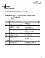
Maintenance

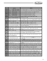
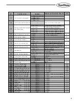
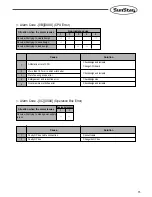
Code description) The 6-digit code appears on the screen as below. Please see the front two digits. 

[02][0100]

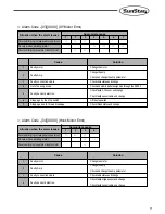
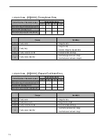
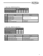
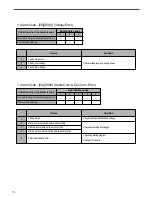
Please cope with problems about each alarm code using the codes below when the error alarm occurs.

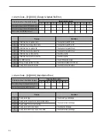
Alarm Code

Delete

Alarm

Alarm Name

Description

Data Read/Write error

Version update error

Main motor operation error

XY motor movement error

Lower shaft motor movement error

Rocking Motor movement error

Presser foot minute adjusting motor

movement error

Input device operation error

Output device operation error

Overvoltage error

Low-voltage error

Serial communication and CAN

communication error

CPU board operating and arithmetic error

Operation box operating error

Design & Update file Error

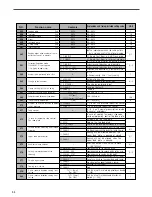
Main Motor Error

XY Motor Error

Hook Motor Error

Turning Motor Error

Pressure Foot Motor Error

Input Error

Output Error

Voltage Error

Serial Com. & Can Com. Error

CPU Error

Operation Box Error

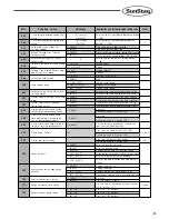
[01][XXXX]

[02][XXXX]

[03][XXXX]

[04][XXXX]

[05][XXXX]

[06][XXXX]

[07][XXXX]

[08][XXXX]

[09][XXXX]

[OA][XXXX]

[OB][XXXX]

[OC][XXXX]

Design

Motor

Input

Output

Voltage

Communication

CPU

OP BOX

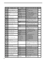
O

X

X

X

X

X

O

O

X

X

O

X

1) Alarm and Warning List [HT-Series Whole Aspect]

Alarm   Code

Summary of Contents for SPS/E-5050 Series

Page 1: ...TARTING USE 2 KEEP THIS MANUAL IN SAFE PLACE FOR REFERENCE WHEN THE MACHINE BREAKS DOWN M ME EE E 1 11 10 03 31 11 1 USER S MANUAL SPS E 5050 8050 Series SPS HT 5050B1 8050B1 Series Large pattern sewing machine parameter setting manual R S Su un nS St ta ar r C CO O L LT TD D ...

Page 2: ......
Page 3: ...h performance powerful operation enhanced durability and more sophisticated design to meet a number of user s needs 2 Please read this user s manual thoroughly before using the machine Make sure to properly use the machine to enjoy its full performance 3 The specifications of the machine are subject to change aimed to enhance product performance without prior notice 4 This product is designed manu...

Page 4: ...N PARAMETER RELATED TO GENERAL SEWING OPERATION 5 1 Function No Related to Pattern Programming 58 2 Pattern chart 60 3 Parameter Number Related to General sewing 62 4 Error List 67 2 Maintenance 69 1 Alarm and Warning List 69 ...
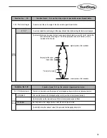
Page 5: ... Caution It is possible to make the feed plate move manually by using direction keys without having relation to setup under the condition of pattern programming It you set up for Disable you can t use the Function No 001 Moving to start position the 2nd origin by manual drive 000 Jog En Dis 1 DISABLE Setting Value It is possible to make the feed plate move by using direction keys Factory installed...
Page 6: ...ng available mode the set sewing available mode becomes unavailable and the machine starts from the sewing operation starts machine for programmed pattern 001 Jog Mode 1 PTN_STR_POS Setting Value It is to set up for the second origin Contents Provided that the feed plate moves manually by using direction keys in the sewing available mode the sewing operation will be started in that point without r...

Page 7: ... move directly to the sewing start position after passing through the machine origin 2 ENABLE It is to decide whether it moves directly to the sewing start position without passing through the machine origin after finishing sewing operation or it moves to the sewing start position through the machine origin It is to move directly to the sewing start position without passing through machine origin ...

Page 8: ... move to the sewing start position after passing through the machine origin Contents The machine moves to the sewing start position after passing through the machine origin everytime after finishing sewing 2 ORG_TO_STR It is to move to the sewing start position after returning to the machine origin by the reverse tracing of sewing patterns Contents After finishing the sewing operation the machine ...

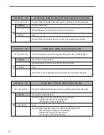
Page 9: ...h operation finishes count the bobbin counter marked on the LCD screen with getting down figures Use that after properly setting the initial default of bobbin counter Caution When the bobbin counter reaches 0 sewing operation will be stopped and Reset Counter appears to indicate the exchange time of bobbin Upon that showing exchange the bobbin and press ESC then the initial default of bobbin count...

Page 10: ...eration will be restarted The ORIGIN key does not operate 2 MANU_TRIM It is to set the time to read pattern from USB flash drive or memory It is available to read patterns just before the preparation for sewing operation Contents The machine can read patterns under the condition that ready lamp for sewing operation turns off Upon reading patterns the ready lamp for sewing operation turns on and be...

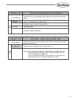
Page 11: ...400 1800 1600 1600 1200 1400 1600 2000 1800 2000 User define 009 Slow Start Speed of Needle Setting Value Acceleration characteristics of sewing speed Number of Needle Characteristics 1 SLOW_STRT0 2 SLOW_STRT1 3 SLOW_STRT2 4 SLOW_STRT3 5 SLOW_STRT4 The 1st Needle speed The 2nd Needle speed The 3rd Needle speed The 4th Needle speed The 5th Needle speed The 6th Needle speed The 7th Needle speed The ...

Page 12: ...unction is used when the set value of Parameter 009 Slow Start Main Shaft Acceleration is 7 User Define 011 User_Slow_2 2 25 100ms Setting Value User sets the speed for the 1st needle User sets the speed for the 1st needle default value 2 100ms Contents This function is used when the set value of Parameter 009 Slow Start Main Shaft Acceleration is 7 User Define 010 User_Slow_1 2 25 100ms Setting V...

Page 13: ...nction is used when the set value of Parameter 009 Slow Start Main Shaft Acceleration is 7 User Define 015 User_Slow_6 2 25 100ms Setting Value User sets the speed for the 5th needle User sets the speed for the 5th needle default value 8 100ms Contents This function is used when the set value of Parameter 009 Slow Start Main Shaft Acceleration is 7 User Define 014 User_Slow_5 2 25 100ms Setting Va...

Page 14: ...unction is used when the set value of Parameter 009 Slow Start Main Shaft Acceleration is 7 User Define 019 User_Slow_10 2 25 100ms Setting Value User sets the speed for the 9th needle User sets the speed for the 9th needle default value 16 100ms Contents This function is used when the set value of Parameter 009 Slow Start Main Shaft Acceleration is 7 User Define 018 User_Slow_9 2 25 100ms Setting...

Page 15: ...sewing speed set within patterns has priority than maximum sewing speed For example though the maximum speed of sewing set as 2700spm if the sewing speed within patterns is set as 2500spm the real speed of sewing is 2500spm It limits the speed under 2500spm 2 2500spm It limits the speed under 2000spm 3 2000spm It limits the speed under 1500spm 4 1500spm Speed 2700 2000 1500 1000 0 Limit of maximum...

Page 16: ... relative position of needle tip based on the needle plate side Set as 0 when the needle tip is positioned on the needle plate side Caution Below figure shows not the real time of feed plate transfer but an adjustment of time angle which an order for feed plate transfer Until the transfer starts after transmitting the order of feed plate transfer delay time exists so the real time angle to start t...

Page 17: ...g start position the condition is maintained At this time it is possible to operate the upper feed plate by the foot switch 2 STRT_HOLD It is to move to the sewing start position under the condition that the upper feed plate is up Contents The machine moves to the sewing start position after finishing sewing operation under the condition that the upper feed plate is up 3 OPEN_STRT It is to move to...

Page 18: ... to set how to treat signal of pedal 1 pedal for upper feed plate The upper feed plate goes down when you step on a pedal once and take off your foot from the pedal Factory installed condition Contents If you step on the pedal 1 pedal for upper feed plate once the signal is treated as effective one even though you take off foot from the pedal and the machine maintains the condition that the upper ...

Page 19: ...rom the pedal 2 the sewing operation will be stopped Ref As above FLIP means a signal system that the signal is treated as an effective one just when the signal is coming just when you step on a pedal 2 FLIP Function No 026 Function Name Setup for presser foot operation It is to set the operation condition of presser foot It is to maintain the presser foot down all the time Contents The machine ma...

Page 20: ...r feed plate descends the presser foot goes down simultaneously 2 WITH_FEED Function No 028 Function Name Setup for wiper operation It is to set the operation and kinds of wiper It is to prohibit the operation of wiper Contents Operation of wiper is prohibited You can set this function when you don t want to use the wiper 028 WP Operation 1 ALWAYS_OFF Setting Value It is to use wiper electronicall...

Page 21: ...tion under the presser foot Contents The wiper is set to operate under the middle presser foot 2 BELW_PF Function No 030 Function Name Setup for thread detection It is not to set to detect thread Related functions Function No 031 Thrd Stitch 1 Function No 032 Thrd Stitch 2 It is not to use the function of thread detection Contents The machine does not stop working till pattern working finishes eve...

Page 22: ...nction is not available if Function No 030 Thrd Detect sets as 1 DISABLE It is to set to detect the number of stitches Factory installed condition 3 Contents If thread is cut during operation the machine detecting the condition directly and make a decision when operation stops For example if you set 0 as soon as the machine detects no thread available the machine stops operation Caution In case th...

Page 23: ...el 1 Speed Level 2 Speed Level 3 Operation time in speed level 3 Operation time in speed level 2 Operation time in speed level 1 It is to set the manual operation of the feed plate to speed up It is to set the time for operation in speed level 2 Factory installed condition 900ms Contents When the feed plate is manually operated by the direction keys it sets the time for feed plate transfer speed l...

Page 24: ...sfer speed at level 3 039 Con Key Tm 3 0 9900ms Setting Value It is to set the feed plate transfer to speed up It is to set the time for operation in speed level 2 Factory installed condition 100ms Contents When pressing the FORW BACK keys continuously to move the feed plate set the time for the transfer speed at level 2 038 Con Key Tm 2 0 9900ms Setting Value It is to set the feed plate transfer ...

Page 25: ... The higher the level the longer the interval between operations On the other hand the wiper may not operate if the level is too low 041 Elc WP Off Tm 0 1020ms Setting Value It is to set the time for the electric wiper operation It is to set the time for the electric wiper operation Factory installed condition 52ms Contents When using the electric wiper set the time for operation The higher the le...

Page 26: ...p after the presser foot has been lowered default value 20ms in case of motor type and 152ms in case of solenoid and pneumatic types Contents 044 PF Down Time 0 1020ms Setting Value It is to set up the standby time till the next operation after the presser foot has been lifted Set up the standby time until the next step after lifting the presser foot default value 20ms in case of motor type and 15...

Page 27: ...gh current flows through Full on time Caution If set too low the solenoid may not operate and when set too high too much electric current may overheat and damage the solenoid and fuse Reference The operation time and strength of the actuators presser foot trimmer wiper which use the solenoid can be adjusted by adjusting the electric current of the solenoid Full on time is the period when the solen...

Page 28: ... thread trimming with electric solenoids the strength of the trimming operation at the beginning can be adjusted by adjusting the Full on time 048 TT Full On Tm 100 1020ms Setting Value It is to set the strength of the thread retaining solenoid operation at the beginning It is to set the time when the maximum current is permitted to solenoid Factory installed condition 200ms Contents In cases of t...

Page 29: ...ration starting power of solenoid in 2step stroke It is to set the time when the maximum current is permitted to solenoid Factory installed condition 200ms Contents In case of using solenoid in 2 step stroke the machine adjusts the time when the maximum current os permitted to solenoid Full on time for setting power when relevant actuator starts operation 052 TSFull On Tm 100 1020ms Setting Value ...

Page 30: ...adjusted current through duty to the solenoid Caution If the default is too small the solenoid may operate only once and spring back to its origin to make sewing impossible On the other hand if it is too large the solenoid may be overheated and it can lead to the damage of solenoid and fuse Reference As seen in the figure duty means a rate of time when signal is lighted on during a period of time ...

Page 31: ...d Factory installed condition 50 Contents In case of thread trimming used with electronic solenoid it sets the power that keeps trimming operation by permitting the adjusted current through duty to the solenoid 056 TT Duty 30 80 Setting Value It is to set the maintenance capacity of the thread retaining solenoid It is to set the amount of maintenance current permitted to solenoid Factory installed...

Page 32: ... to set the maintenance capacity of solenoid in 2 step stroke It is to set the amount of maintenance current permitted to solenoid Factory installed condition 80 Contents In case of using solenoid in 2 step stroke it sets the power that keeps the relevant operation by permitting the adjusted current through duty to the solenoid 060 TS Duty 30 80 Setting Value It is to set the maintenance capacity ...

Page 33: ...he current sewing work and move to the programming status to program new pattern you can store your new pattern in the same pattern number as the one before on the USB flash drive However internal memory will still retain the previous pattern shapes thus the previous pattern will be called and you might think that your new programmed pattern is not stored properly Refer to 2 3 Check and delete pat...

Page 34: ...ode using the stitch length Factory installed condition Contents While the number of stitches are the same the length of the stitches along the X and Y axis are adjusted according to the magnifying demagnifying rate Set the rate within the feed plate transfer limit 2 STITCH_LEN It is to set the magnifying demagnifying mode using the number of stitches Contents While the length of stitches are the ...

Page 35: ...r set as 3 It is to set the mode of stopping one pattern and transferring to the next pattern The pattern is read and transferred manually Contents While chain sewing the machine stops when the pattern is stopped Press the ENTER key to read and sew the next pattern 065 Chain Select 1 MANUAL Setting Value The next pattern is read and transferred automatically Factory Installed Condition Contents Wh...

Page 36: ... decelerating speed is set here 068 Decel SPM Trim 200 400spm Setting Value Function No 066 Function Name Set the clamp when the chain is used When the chain function is used the clamp up down can be set The clamp down setting is unused default The clamp down setting is used Contents In case where three patterns are used consecutively when the first pattern work is finished the second pattern is a...

Page 37: ... in case pneumatic kinds the error is marked on the screen to inform users 2 ENABLE Function No 069 Function Name Thread trimming delayed time It is to set the delayed time before the wiper is operated after the thread is trimmed It is to set the delayed time after thread trimming Factory installed condition 72 Contents It is to set the delayed time of the wiper operation after the thread has been...

Page 38: ...red first Feed plate raised and stopped Feed plate raised and stopped Both parts raised and stopped Left side raised and stopped only Right side raised and stopped only Both parts raised and stopped Left side raised and stopped only Right side raised and stopped only Both parts raised and stopped Left side raised and stopped only Both parts raised and stopped Right side raised and stopped only Bot...

Page 39: ...ration the upper feed plates are all kept in the raised position In this case the upper feed plates can be controlled with the pedal 2 OPEN Follow the instructions in 060 Upper Feed Plate Control When Paused Factory installed condition Contents Follow the instructions in 060 Upper Feed Plate Control When Paused 3 FF_NUMBER Function No 073 Function Name Whether to use thread tension adjusting plate...

Page 40: ... allowed when the upper feed plate is opened Factory Default Contents Only in case of closing the upper feed plate press the left switch on the stepping stand to start sewing 2 ENABLE Function No 075 Function Name Back Forth jump stitches User can define stitch value to move 1 1 1 10 00 0 S St ti it tc ch h Contents To confirm the pattern with the back forth stitch function the user can set the st...

Page 41: ...CO ON ND D_ _O OR RG G Z Zo oo om mi in ng g b ba as se ed d o on n t th he e r re ef fe er re en nc ce e o on n t th he e s se ew wi in ng g s st ta ar rt ti in ng g p po oi in nt t Contents Zooming based on the first stitch of any pattern design 3 3 S SE EW WI IN NG G_ _S ST TR RT T Z Zo oo om mi in ng g b ba as se ed d o on n t th h r re ef fe er re en nc ce e p po oi in nt t d de ef fi in ne e...

Page 42: ...etting Value Contents The user can expand the size of sewing limit in the program Caution The feeding axis must be changed in line with the size of sewing limit where mechanical feeding is possible If the user increases the set up value in the program and begins feeding the machine can be severely damaged Function No 080 Function Name X axis reverse direction sewing limit set up T Th he e u us se ...

Page 43: ... t t th he e s si iz ze e o of f Y Y a ax xi is s r re ev ve er rs se e d di ir re ec ct ti io on n a as s d de es si ir re ed d Factory default 50 1 50mm Default value is same to that of 5050 model Default values may differ depending on models 082 YMINUS Limit 1 250 Setting Value Contents The user can expand the size of sewing limit in the program Caution The feeding axis must be changed in line ...

Page 44: ...ng reverse rotation after trimming I It t i is s t to o s se et t r re ev ve er rs se e r ro ot ta at ti io on n a af ft te er r t tr ri im mm mi in ng g N No ot t i in n u us se e a at t t th he e f fa ac ct to or ry y Contents It will not apply reverse rotation after trimming 084 RevAfterTrim 1 DISABLE Setting Value I In n u us se e Contents After trimming the reverse rotation function can be ap...

Page 45: ...me Jump Speed Setting This function is to set the jump speed It sets the slowest jump speed Contents It sets the medium jump speed default Contents It sets the highest jump speed Contents To shorten the working hours set the highest jump speed It could save plenty of time 089 Jump Speed 1 SLOW_SPEED 2 MIDDLE_SPEED 3 FAST_SPEED Setting Value Function No 088 Function Name Setting the Safety Mode T T...

Page 46: ...e presser foot If the interference of the presser foot is not concerned during the jump motion this function can be used to save work hours Contents During the jump motion the jump motion is conducted with the presser foot lifted If the interference of the presser foot occurs during the jump motion this function can be used 091 Jump PF Ctrl 1 DISABLE 2 ENABLE Setting Value Function No 092 Function...

Page 47: ...50 8050 does not have the motor enabling delicate clamp adjustment Therefore this function cannot be used and it is set at disabled all the time 094 Clamp Data 1 DISABLE Setting Value Function Name PF Height Control Enable Disable limited to the presser foot motor equipped models User enables or disables the function of controlling presser foot height User can set the range of the vertical movemen...

Page 48: ...re this function cannot be used 096 Clamp Range 000 350 0 05mm Setting Value Function Name Presser Foot Height Setting limited to the presser foot motor equipped models User sets the presser foot height User sets the presser foot height default value 000 mm Contents Use the direction keys 2 8 to choose the clamp height and save the value When the keys are pressed the clamp position can be checked ...

Page 49: ...AT_BCODE setting Contents Use the fixed type bar code to automatically call designs and make an auto start When work is done it moves to the barcode origin point 6 SFAT_BCODE Function No 099 Function Name Sewing ready setting upon design auto call When designs are called automatically it sets the use of sewing ready function The function is disabled Contents When designs are called automatically w...

Page 50: ... operation delay time for the design auto call sensor SEN_0 SEN_7 10 100ms Contents It sets the time taken before the next sensor s sensing The basic unit is 100ms If 10 is set as parameter it refers to 1000ms or one second The function is designed to ensure accurate sensing by creating time delay in sensing between a sensor and the next sensor 101 Auto Call TM 1 DISABLE Setting Value Function No ...

Page 51: ...the saved designs 2 ENABLE Function No 105 Function Name Upper Lower Shaft Origin Search Motion Setting Set the upper lower shaft origin search motion after sewing completion Not used Contents The upper lower shaft origin search motion does not take place 105 Hook ORG Mode 1 JOB_SETUP Origin search takes place after trimming Contents After trimming the upper lower shaft origin search takes place 3...

Page 52: ...after the sewing is completed enable this function 2 HEAD_UP Function Name Oil Spray Time Setting Set the oil spray time unit 25ms Set the oil spray time default value 40 Contents To prevent dust gathering and thread cut entanglement around the hook oil is sprayed according to the time set at 108 OilOffTIme 107 Oil Control 00 250 ms Setting Value Function No 107 Function Name Set the oil spraying ...

Page 53: ...e needle thread after trimming 109 ThHold En Dis 1 DISABLE Setting Value The upper thread holing function is used Contents After trimming the upper thread holder holds the needle thread during the time set at 10 ThreadHoleTm 2 ENABLE Function No 110 Function No 111 Function Name Needle Cooling Setting The needle temperature rises due to the friction between the sewing material and the needle Cold ...

Page 54: ...n No 112 Function No 113 Function No 114 Function Name Trimming method setting The upper or lower thread trimming can be set using trimming setting items T Tr ri im m b bo ot th h t th he e u up pp pe er r a an nd d l lo ow we er r t th hr re ea ad ds s D De ef fa au ul lt t v va al lu ue e 2 27 7 Contents 114 Set Trimmer 1 STANDARD Setting Value T Th he e l lo ow we er r t th hr re ea ad d o on n...

Page 55: ...e machine does not operate This function applies when the removable clamp is used Cassette zig model The clamp sensor is not used Contents Even though the sensor does not detect the clamp forcible sewing is possible 116 Clamp Sensor 1 DISABLE Setting Value The clamp sensor is used When the function is tried to use without the attachment of the cassette zig the sewing is not started Contents If eit...

Page 56: ... the pneumatic trimmer It is not applicable to the cap trimming method By nature of the device or sewing materials some difference is found in the trimmers entry angle A user can adjust the trimmer blade entry angle by using parameters Contents In general the most stable trimming angles are between 20 and 40 119 Trim St Angle 0 50 Setting Value Highest position of the needle bar Entry angle of the...

Page 57: ...d Angle 0 100 Setting Value Highest position of the needle bar Entry angle of the upper thread holder Trimmer entry angle Lowest position of the needle bar Function No 121 Function Name Set up the presser stepped pulley motor Function to decide to use the pressure foot stepped pulley motor air compressed wiper Not use the pressure foot stepped pulley motor use the air compressed wiper Contents Set...

Page 58: ...ts Same as normal use when this function is not selected In use Contents The entry to the program mode is prevented when this function is selected 123 Program Lock 1 DISABLE 2 ENABLE Setting Value Function No 124 Function Name Setting the default position of the clamp This sets the default position of the clamp A user can switch the pneumatic lines of the clamp The function is disabled default Con...

Page 59: ...t the current angle value By nature of SPS E 5050 and 8050 the head is lifted and the main shaft motor is attached at the angle of 90 Therefore the default value is set at 97 126 Up Stop Pos 0 360 degree Setting Value Function No 126 Function No 125 Function Name Air Bag Mode Setting Air Bag specification Function to open the air compressed thread release unit when users move without trimming at t...

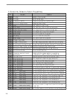
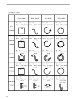
Page 60: ...fixed part of sewing shape Read the stored pattern from USB flash drive Store the programmed pattern into USB flash drive Format the USB flash drive Absolute coordinate system relative coordinate system Use straight line to create the zigzag sewing data Use curve to create the zigzag sewing data Use arc to create the zigzag sewing data Use circle to create the zigzag sewing data Set the distance b...

Page 61: ...gnal of the extended I O board Turn on off the 3rd thread adjusting device with output port signal The designs and the properties can be modified by setting the section 035 036 037 038 039 040 042 043 044 046 048 055 056 057 058 059 61 62 63 64 041 045 NO Function Contents It is the function to prevent stitches from being untangled by making stitch width condensed in sewing start part and sewing e...

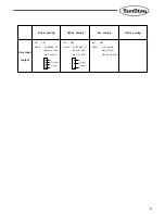
Page 62: ...ig zag sewing No 022 Name Circle zig zag sewing No 027 Name Linear double sewing No 028 Name Spline double sewing No 029 Name Arc double sewing No 030 Name Circle double sewing No 035 Name Linear reverse sewing No 036 Name Spline reverse sewing No 037 Name Arc reverse sewing No 038 Name Circle reverse sewing Date input output No 057 Name Output port control No 058 Name Input port control No 059 Na...

Page 63: ...sewing Arc sewing Circle sewing Date input output NO 061 Name Extended I O board output port control NO 062 Name Extended I O board input port control NO 063 Name 3rd thread adjustment Device control Output signal Input signal ...

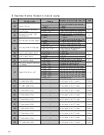
Page 64: ...ugh the shortest route 2 ORG_TO_STRT 2 After returning to the original point return to the starting point 3 REV_ORG_STRT 3 After returning to the origin point by tracing the pattern shape back 1 UP_COUNT 1 Count up 2 DN_COUNT 2 Count down 1 DISABLE 1 No use 2 ENABLE 2 Use 1 JOB_SETUP 1 Before completion for sewing preparation 2 JOB_READY 2 After completion for sewing preparation 1 AUTO_TRIM 1 Perf...

Page 65: ...t in condition of 2 step rise 0 1 0 1 1 1 0 1 100 100 100 100 100 100 4 4 4 4 4 4 4 4 4 4 4 4 4 4 1 029 Position of wiper operation Thread broken sensor mode Detected no of broken stitches when starting sewing Detected no of broken stitches during the normal sewing Trimming mode Time of 1st step jog speed Time of 2nd step jog speed Time of 3sd step jog speed 1st step key continued pressing time 2n...

Page 66: ... 50 1 50mm For 5050 X axis reverse direction sewing limit set up 080 Sets the size of X axis backward direction as desired 1 250 070 Whether to use the function to detect fall of pressure 1 DISABLE 2 ENABLE 1 Do not use pressure reduction sensor 2 Use pressure reduction sensor NO Function name Contents Explanation and factory installed setting value Unit 1 10 10 10 10 10 10 0 1 0 2 1 0 2 1 100 Fee...

Page 67: ...s Fabric Thickness Control Code Setting 1 DISABLE 2 ENABLE The presser foot s fabric thickness control code is not used The presser foot s fabric thickness control code is used 1 SAVE 2 DELETE 093 Clamp move enable disable limited to the clamp motor equipped models 1 DISABLE Not used Cannot be used in E Series 5050 097 Presser foot height setting User sets the presser foot height Cannot be used in...

Page 68: ...ard Not used Give a preview of saved designs Does not search the upper lower shaft origin Search the upper lower shaft origin Search the origin after trimming Does not move up the head Move up the head Move up the head during the jump motion Set the oil spray time 00 10 x 4 ms This function is to set the cycle of ending oil spraying motion 00 50 sec Not used The thread holder function used after t...

Page 69: ...pressed when Power On In case that the Left Switch is pressed when Power On In case that the TwoStage Switch is pressed when Power On Abnormalities on the communication between the main shaft and the I O board Unknown error Unknown error Lower shaft origin is not found SPS C Series A problem detected in lower shaft motor SPS C Series A problem detected in Y shaft motor SPS C Series A problem detec...

Page 70: ...rror in case of the connection P U during power on Error in case of the connection P U during power on Main shaft synchro error Not used Main shaft overload error No USB inserted error Upper shaft rocking motor movement error Lower shaft rocking motor movement error Upper shaft rocking motor origin motion error Lower shaft rocking motor origin motion error Message Main Motor Err nDismatch n999 Ove...

Page 71: ...error Input device operation error Output device operation error Overvoltage error Low voltage error Serial communication and CAN communication error CPU board operating and arithmetic error Operation box operating error Design Update file Error Main Motor Error XY Motor Error Hook Motor Error Turning Motor Error Pressure Foot Motor Error Input Error Output Error Voltage Error Serial Com Can Com E...

Page 72: ...ck pattern data 001 999 Check update file pattern1 exe Check update file pattern1 exe Check Para dat file Check Para dat file Check USB insertion status Check format method FAT FAT32 Check cable connection status 1 2 3 4 5 6 7 8 9 Cause Solution Occurs while trying to make power supply turn on Occurs while trying to operate the motor Situation when the alarm issues Appropriate cause 1 2 3 4 5 Alar...

Page 73: ...d modify patter design size through the SSP5 0 Check faulty X Y sensor and change Check faulty sensor cable and change Lift the stop switch Check thread status and change 1 2 3 4 5 6 7 Cause Solution Occurs while trying to make power supply turn on Occurs while operating motor Occurs while trying to operate or stop the motor Situation when the alarm issues Appropriate cause 1 2 3 4 Alarm Code 04 X...

Page 74: ...nd change Check faulty origin sensor and change Check faulty sensor cable and change체 1 2 3 4 Cause Solution Occurs while trying to make power supply turn on Occurs while operating motor Occurs while trying to operate or stop the motor Situation when the alarm issues Appropriate cause 1 2 3 4 Alarm Code 06 XXXX Pressure Foot Motor Error Faulty motor Faulty driver board Faulty connection cable Faul...

Page 75: ...cable Check switch status and cancel Change the switch Change the cable 1 3 4 4 5 Cause Solution Occurs while trying to make power supply turn on Occurs while stitching Occurs when starting stitch Situation when the alarm issues Appropriate cause 1 2 3 Alarm Code 08 XXXX Output Error Pneumatic pressure decreases Pneumatic cable is not connected Faulty lower feed plate connection Check pneumatic le...

Page 76: ...lution Occurs while trying to make power supply turn on Occurs while stitching Situation when the alarm issues Appropriate cause 1 2 3 4 5 Alarm Code 0A XXXX Serial Com Can Com Error Faulty motor Motor communication cable abnormality Cable abnormality on the motor UVW Main board communication cable abnormality CAN initialization error Check motor specification and change Check cable status and cha...

Page 77: ... Out of sewing scope error Enlargement and reduction error Over maximum stitches error Check design and recreate Change CPU board Check design and recreate Check design size Check design and recreate 1 2 3 4 5 Cause Solution Occurs while trying to make power supply turn on Situation when the alarm issues Appropriate cause 1 2 Alarm Code 0C XXXX Operation Box Error Faulty OP box cable connection Fa...

Page 78: ...i i n n i i t t i i a a l l v v a a l l u u e e w w i i t t h h d d i i g g i i t t k k e e y y s s I I n n p p u u t t o o f f p p a a t t t t e e r r n n n n o o w w i i t t h h d d i i g g i i t t k k e e y y s s S S t t a a r r t t i i n n g g b b y y l l e e f f t t p p e e d d a a l l E E n n d d i i n n g g b b y y r r i i g g h h t t p p e e d d a a l l I I n n p p u u t t o o f f s s e e ...

Page 79: ...e Speed Setting 2 nd Needle Speed Setting 3 rd Needle Speed Setting 4 th Needle Speed Setting 5 th Needle Speed Setting 6 th Needle Speed Setting 7 th Needle Speed Setting 8 th Needle Speed Setting 9 th Needle Speed Setting 10 th Needle Speed Setting Maximum speed limit of sewing Opening angle of feed plate transfer Operation condition of feed plate when sewing operation finishes Descent maintenan...

Reviews: